
The regular field-of-view (RFoV) ITS-in-a-box (revision 1a) consists of a plastic box that's laser cut from computer-aided design (CAD) drawings, a chart tablet, and a device under test (DUT). The RFoV ITS-in-a-box is designed to test devices with an FoV less than 90 degrees (RFoV). You can purchase an ITS-in-a-box or build your own.
The rev1b version of the RFOV ITS-in-a-box adds support for modular components and is compatible with the tele extension rig.
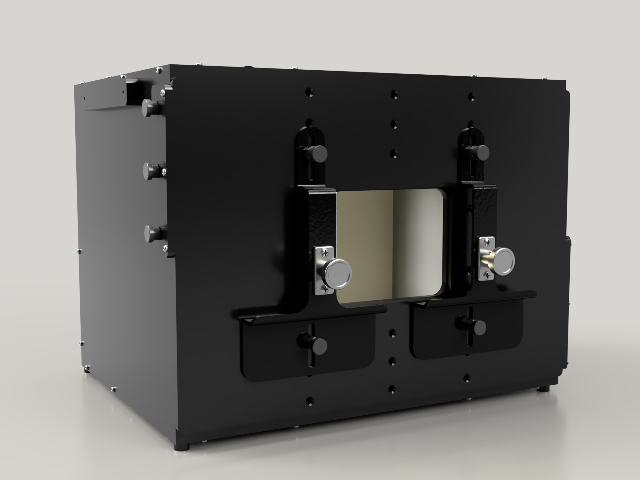
Figure 1. Regular field-of-view (RFoV) ITS box Rev1b
Revision history
The following table describes the revision history of the regular field-of-view box and includes download links to each version of the production files.
| Date | Revision | Production file download | Change log |
|---|---|---|---|
| September 2024 | 1b | Rev. 1b production files |
|
| May 2019 | 1a | Rev. 1a production files |
|
Purchase an RFoV ITS-in-a-box
We recommend purchasing an RFoV ITS-in-a-box (revision 1a) from one of the following qualified vendors.
Byte Bridge Inc.
USA: 1502 Crocker Ave, Hayward, CA 94544-7037
China: 22F #06-08, Hongwell International Plaza Tower A, 1600 West Zhongshan Road, Xuhui, Shanghai, 200235
www.bytebt.com
androidpartner@bytebt.com
USA: +1-510-373-8899
China: +86-400-8866-490JFT CO LTD 捷富通科技有限公司 (previously known as MYWAY DESIGN)
No. 40, Lane 22, Heai Road, Wujing Town, Minhang District, Shanghai, China
4F., No. 163, Fu-Ying Road, XinZhuang District, New Taipei City 242, Taiwan
www.jftcoltd.com
service@jfttec.com or its.sales@jfttec.com
China:+86-021-64909136
Taiwan: 886-2-29089060
Video tutorial
This is a video tutorial on how to set up the RFoV ITS-in-a-box.
Build an RFoV ITS-in-a-box
Instead of purchasing an RFoV ITS-in-a-box, you may build your own. This section provides detailed instructions for assembly.
Mechanical drawings
The ITS-in-a-box consists of a DUT, a chart tablet, an internal lighting system, and a plastic box that's laser cut from CAD drawings (shown in Figure 1).
To get started, download the latest production file.
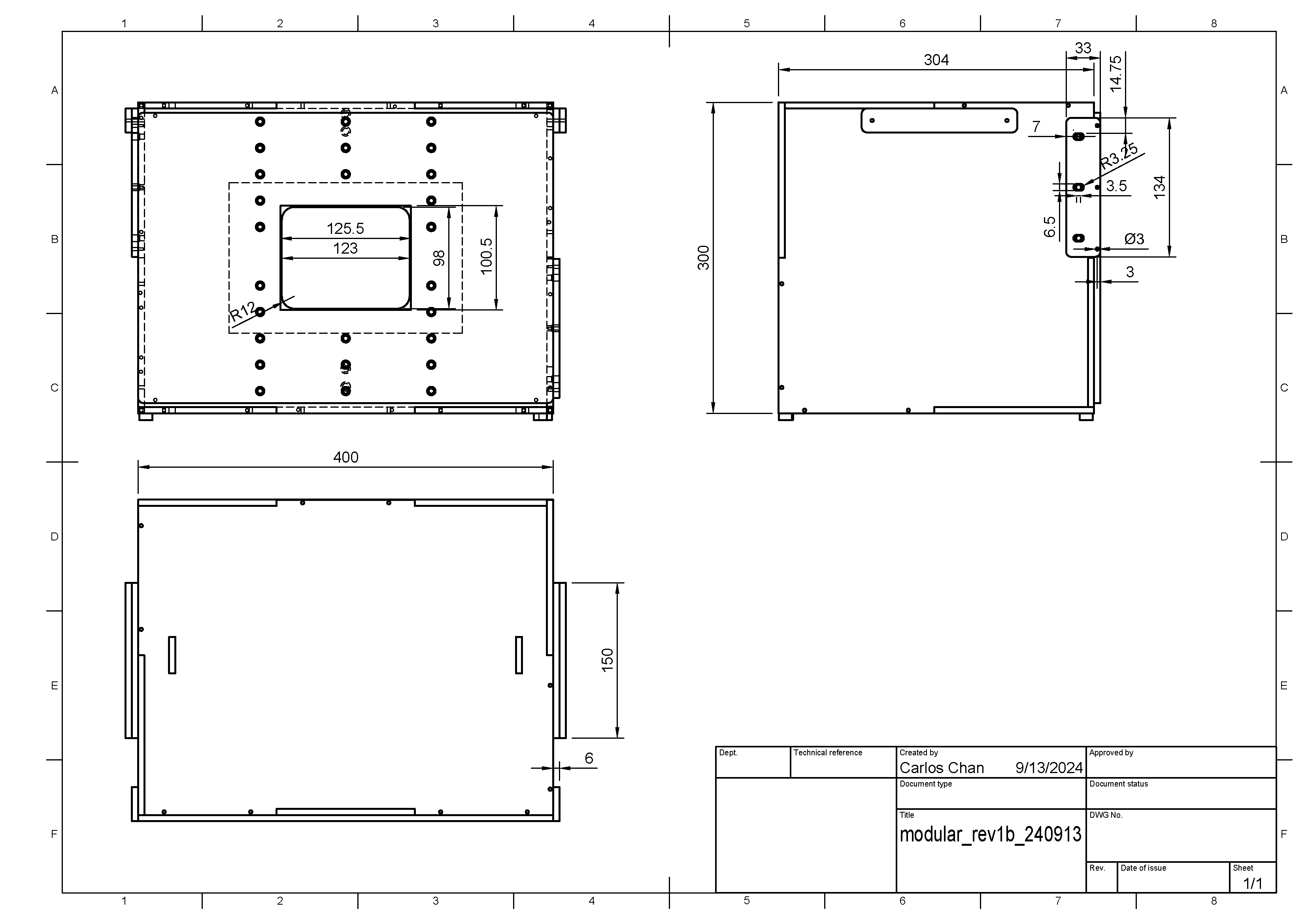
Figure 2. Mechanical drawing of ITS-in-a-box
Purchase the hardware from the bill of materials (BOM). Cut the plastic and vinyl pieces.
Required tools
Have the following tools available:
- Torx head screwdriver
- Power drill
- ABS glue
- Needle nose pliers
- X-ACTO knife
- Wire cutters or scissors (optional)
Step 1: Apply vinyl and glue feet
Apply colored vinyl on the smooth side of the acrylonitrile butadiene styrene (ABS) and cut out the necessary openings as shown in Figure 3 and 4. Apply the white vinyl with the large rectangular opening on the tablet side of the box and the black vinyl with the circular opening on the mobile device side of the box. Apply gray vinyl on the side panels as shown in Figure 4 and glue the feet on the four corners of the bottom panel as shown in Figure 5. For more information, see wikiHow.
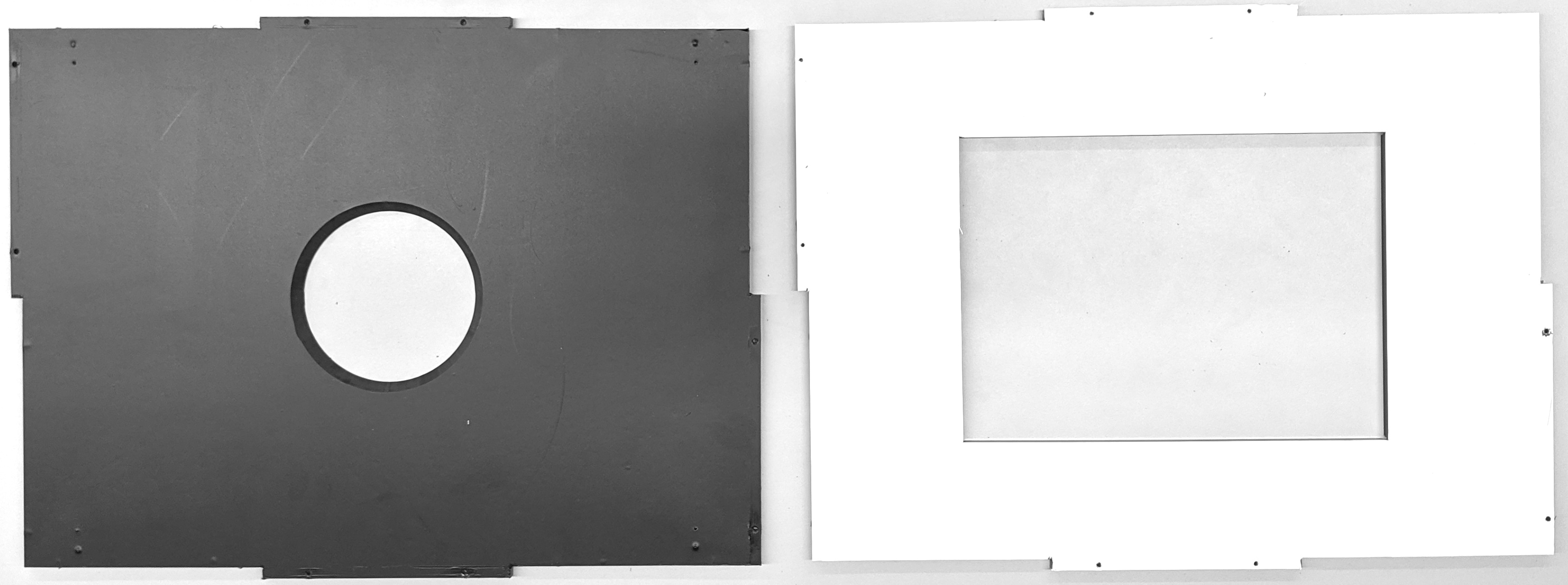
Figure 3. Black vinyl on front panel (left), and white vinyl on back panel (right)
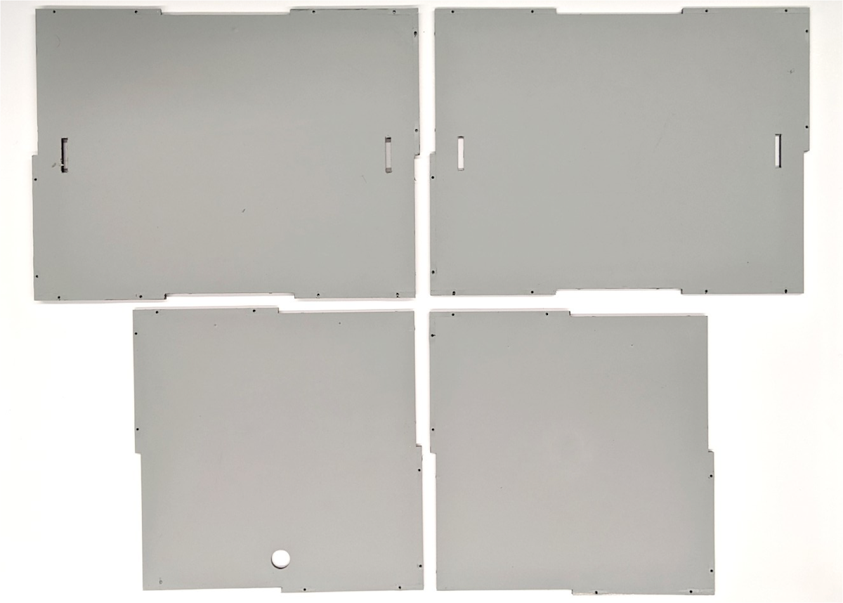
Figure 4. Gray vinyl on side panels
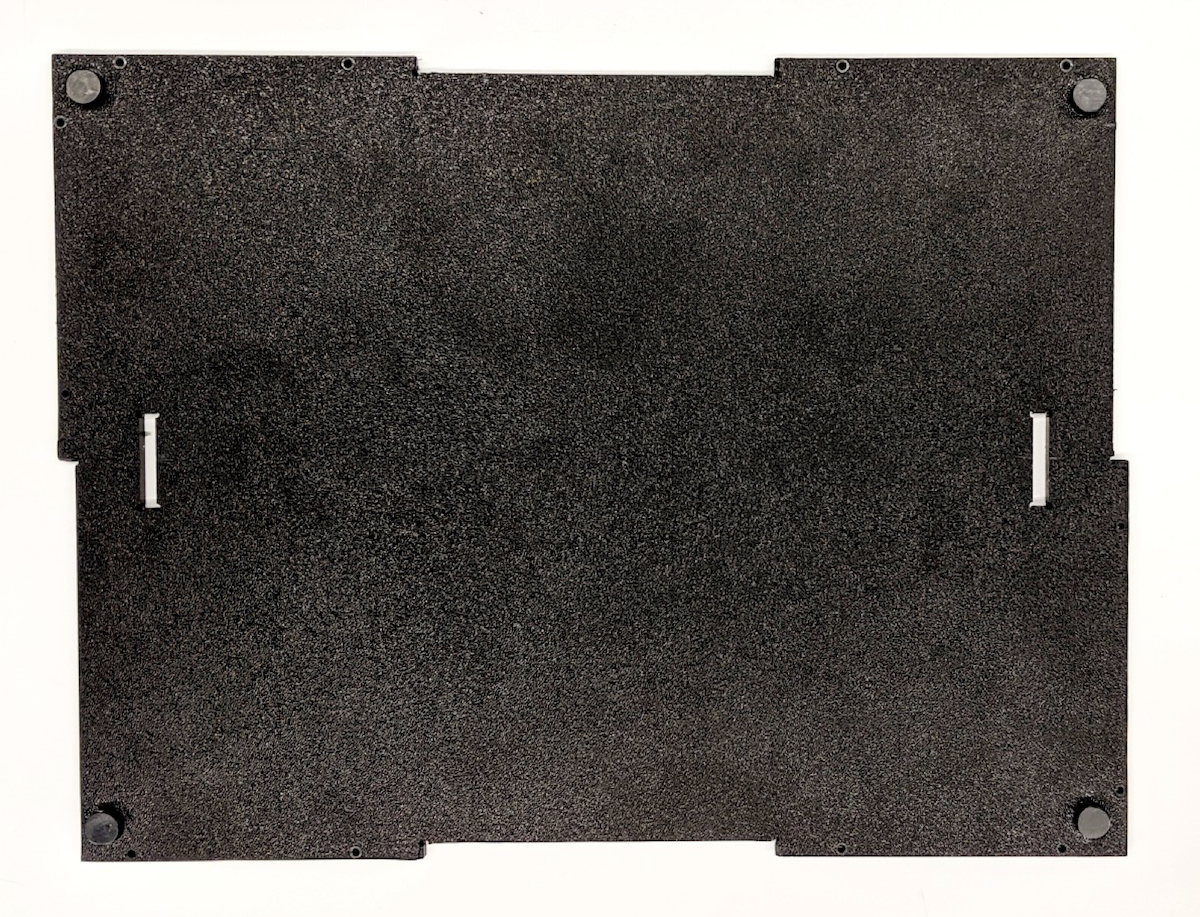
Figure 5. Feet on the four corners of the bottom panel
Step 2: Lighting
To assemble the ITS-in-a-box lighting component:
Gather the lighting hardware as shown in Figure 6.
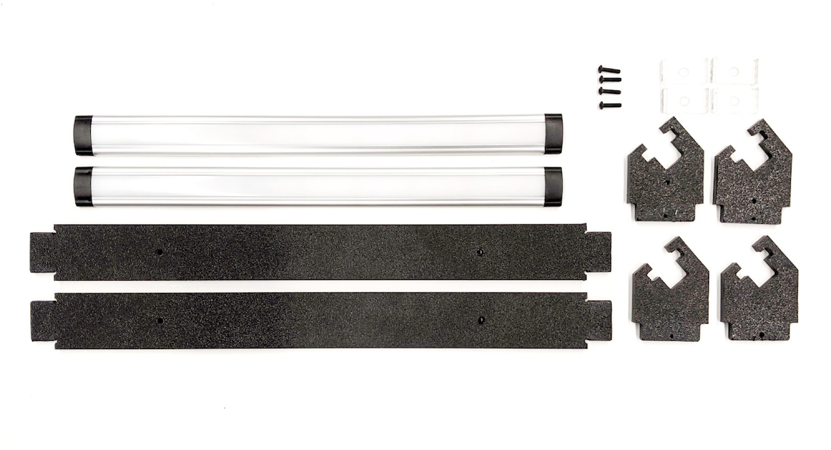
Figure 6. Light assembly parts
Hardware includes the LED light bars, plastic light baffles, plastic light mounts, plastic or metal light clips included in the LED lighting kit, and four 6-32 screws with acorn head nuts.
Bolt the light clips to the plastic baffles as shown in Figure 7. Secure the clips using the acorn nuts on the other side of the baffles.
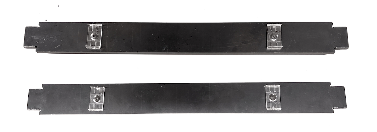
Figure 7. Plastic baffles with light clips attached
To assemble the lights, attach the plastic baffles to the back of the LED light bars using the light clips.
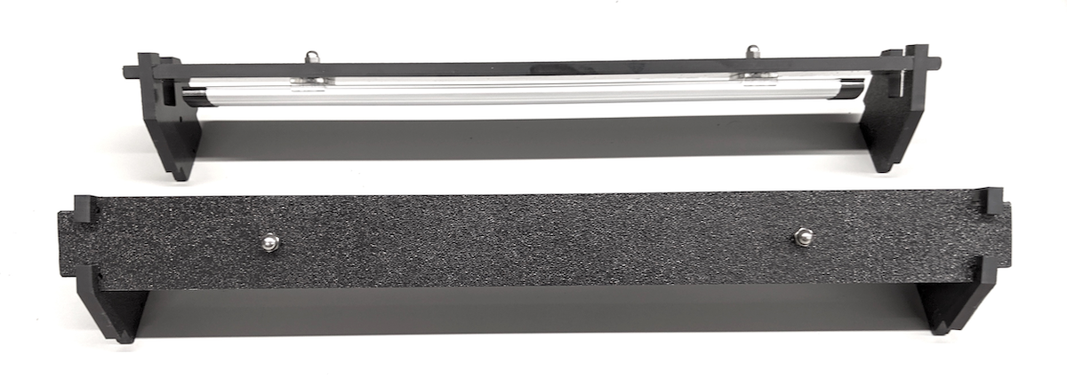
Figure 8. Light bars with the lights facing down and screws threaded through the clips
When the lighting component is assembled, the LED light bars should point down, and the plastic baffles should cover the shiny, reflective surface on the back of the LED light bar.
Step 3: Phone mounts
To assemble the phone mounts:
Gather the required items as shown in Figure 9.
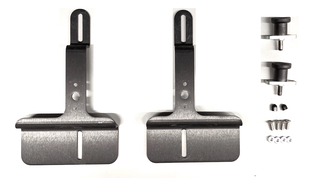
Figure 9. Phone mount items
The hardware includes two metal phone mounts, two plungers, two rubber tips, four 8-32 pan-head screws, and the corresponding nuts.
Cut the rubber tips short enough to not interfere with plunger operation (roughly in half), then apply the rubber tips to cover the tips of the plungers.
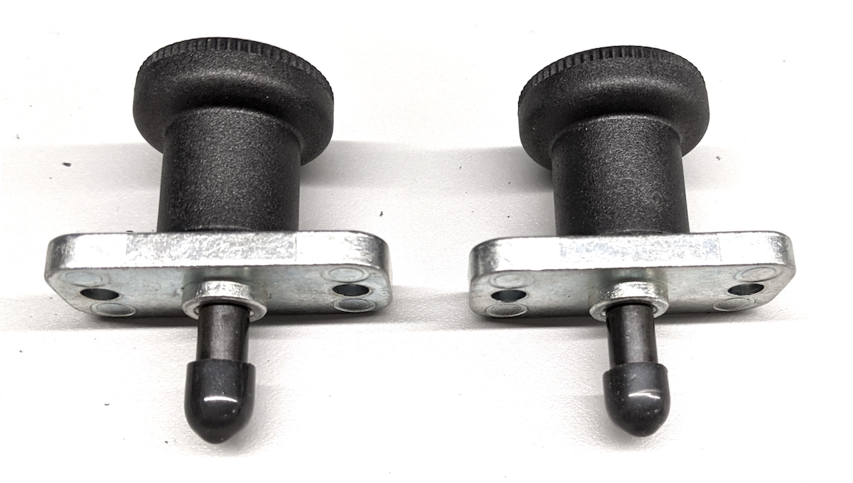
Figure 10. Plungers with rubber tips
Assemble the phone mounts using pan-head screws to attach the plunger mechanisms to the metal mounts. Ensure that the screws are tightened with the corresponding nuts.
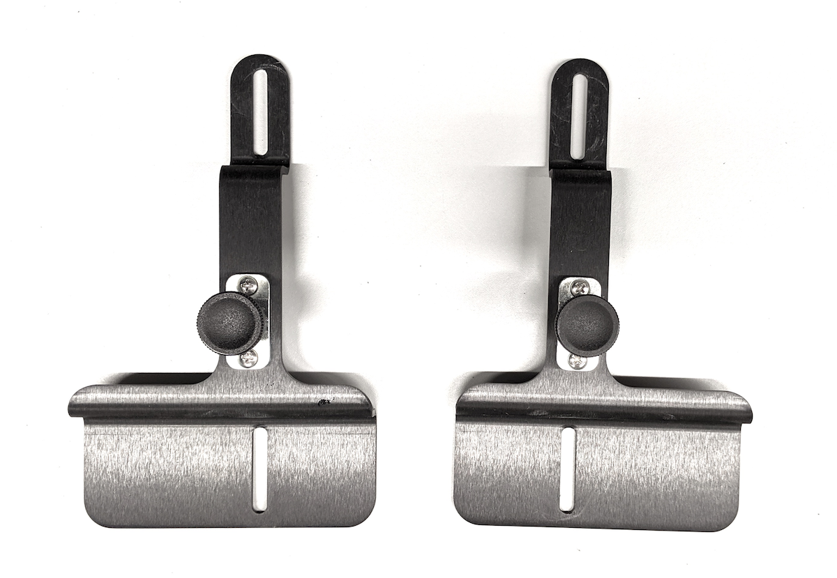
Figure 11. Assembled phone mounts
Step 4: Aperture plate
To assemble the front aperture plate:
Gather the front aperture plate hardware shown in Figure 12.

Figure 12. Front aperture plate assembly parts
Hardware includes the assembled phone mounts, the phone mount panel, four short nylon screws, and four nylon nuts (required to keep the screws from protruding through the back of the plastic plate).
Using the screws and nuts, secure the assembled phone mounts to the phone mount panel. Make sure that the phone mounts are in the correct orientation as shown in Figure 13.
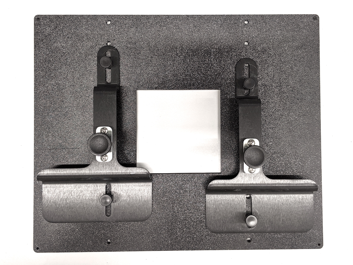
Figure 13. Assembled front aperture plate
Step 5: Tablet mount
To assemble the table mount:
Gather the tablet mount assembly hardware shown in Figure 14.
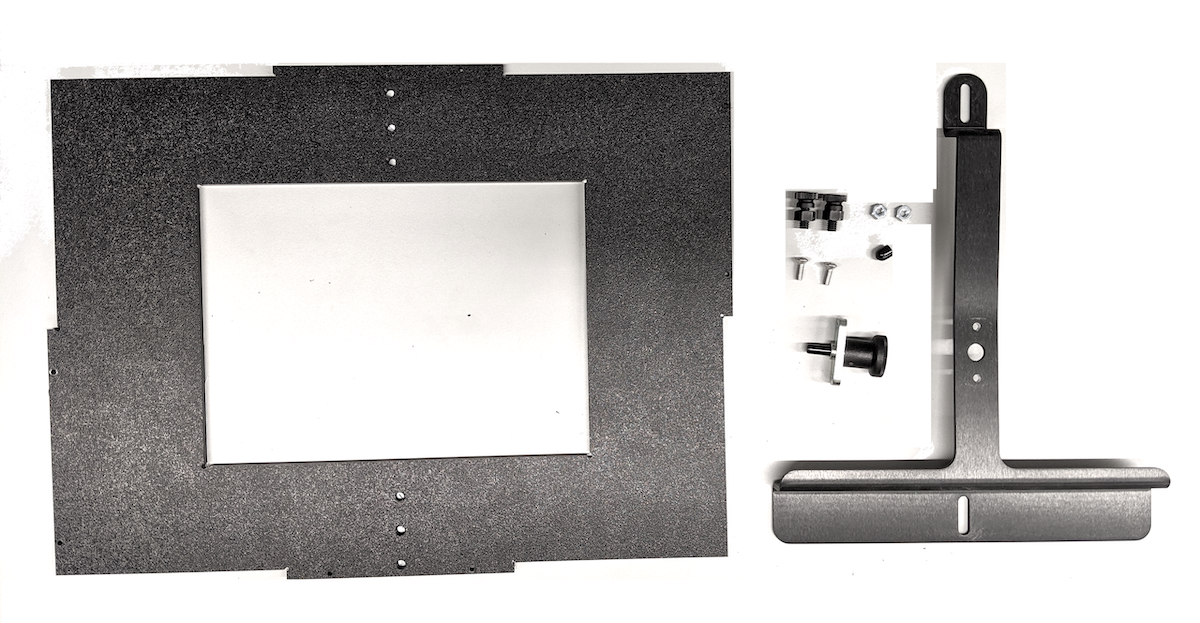
Figure 14. Tablet mount space assembly parts
Hardware includes the back panel, tablet mount, one plunger, one rubber tip, two 8-32 pan-head screws, two short nylon screws, and the corresponding nuts.
Assemble the tablet mount by using pan-head screws to attach the plunger mechanisms to the metal mount. Ensure the screws are tightened with the corresponding nuts.
Using the screws and nuts, secure the assembled tablet mount to the back panel. Make sure that the phone mounts are in the correct orientation as shown in Figure 15.
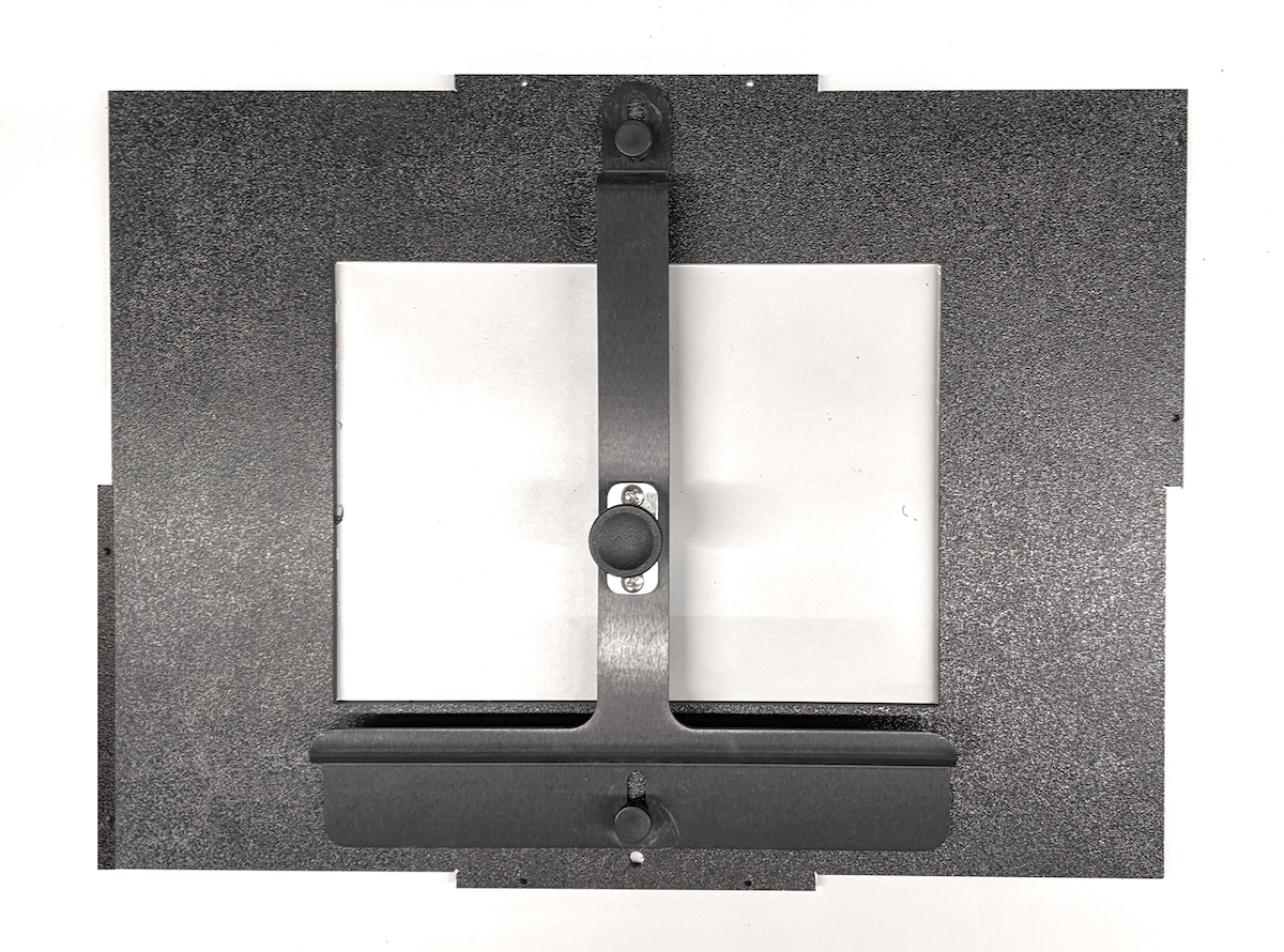
Figure 15. Assembled tablet mount
Step 6: Install lights
To install the lights:
Install the light baffles on the top and bottom panels as shown in Figure 16.
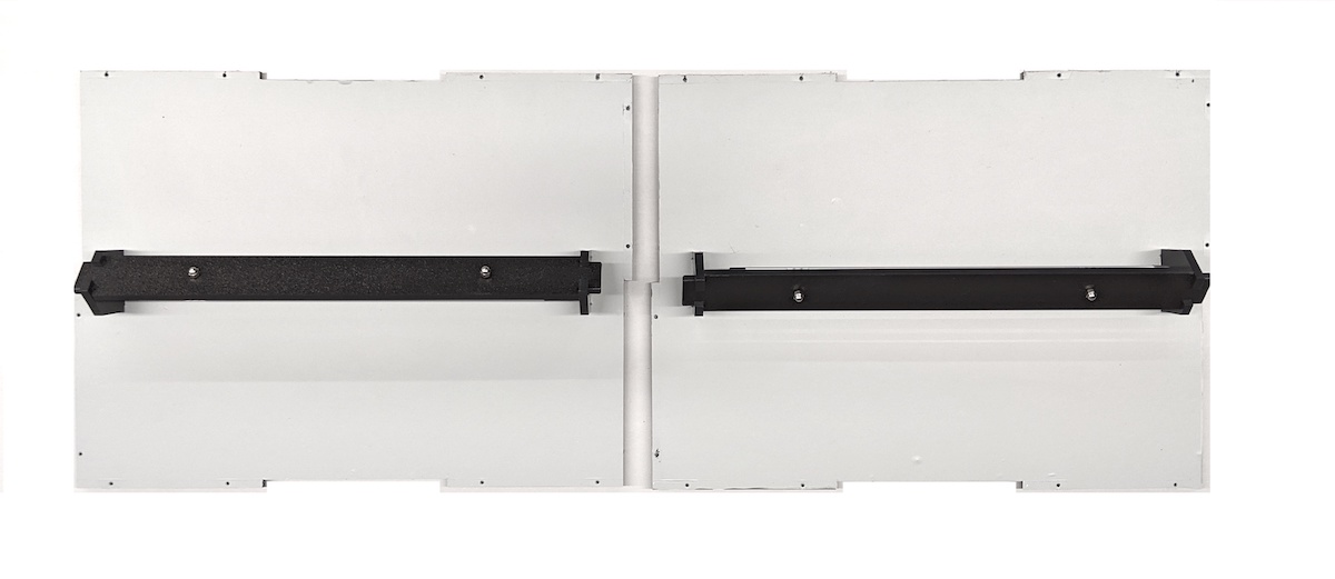
Figure 16. Light baffles installed on the top and bottom panels
Secure the light baffles by squeezing the pin into the small hole on the rectangular tab that extends through the slot in the top and bottom panel as in Figure 17.
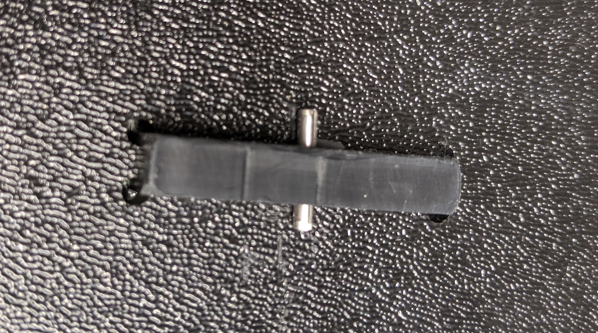
Figure 17. Close up of inserted pin in LED mount tab on outside of box
To secure the pins, gently squeeze the pins until you feel some pressure on the plastic as the pins are secured into place.
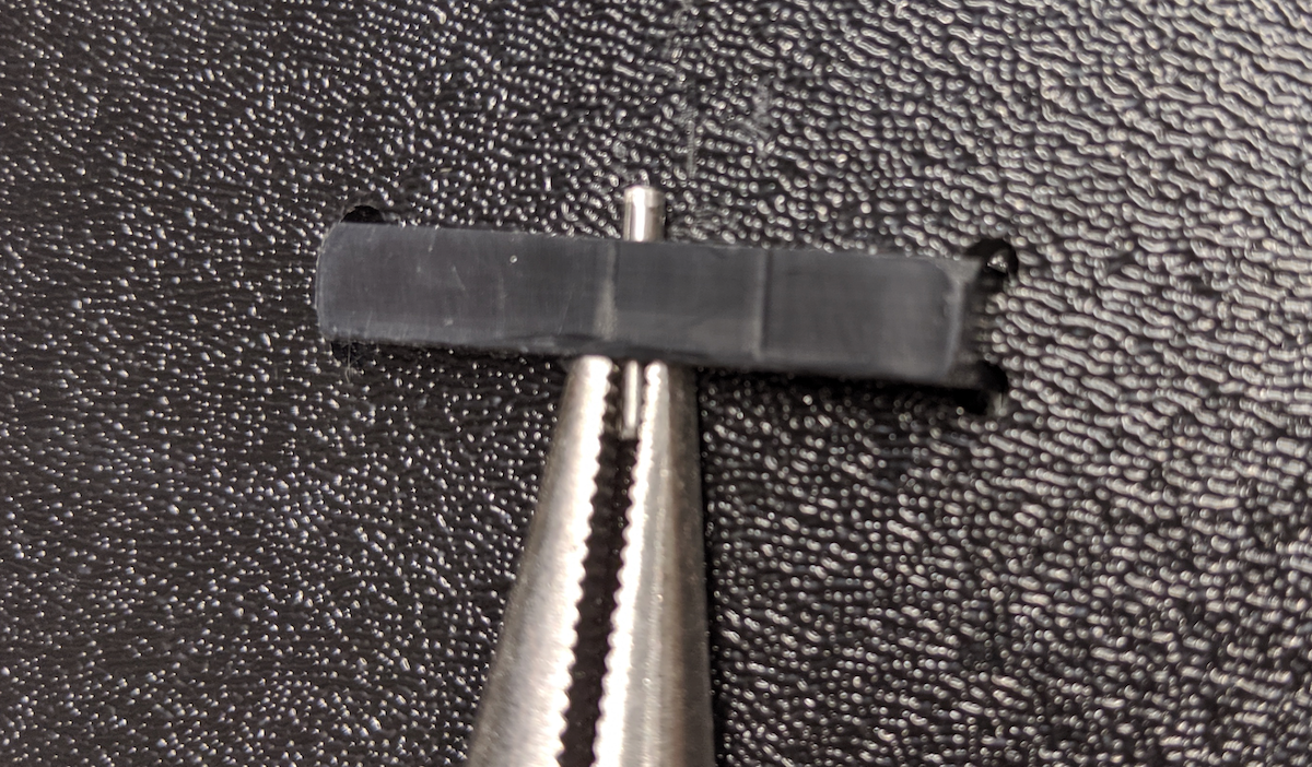
Figure 18. Pliers used to install pin
Assemble the front and side panels in the correct orientation as shown in Figure 19, and tape them together from the exterior.
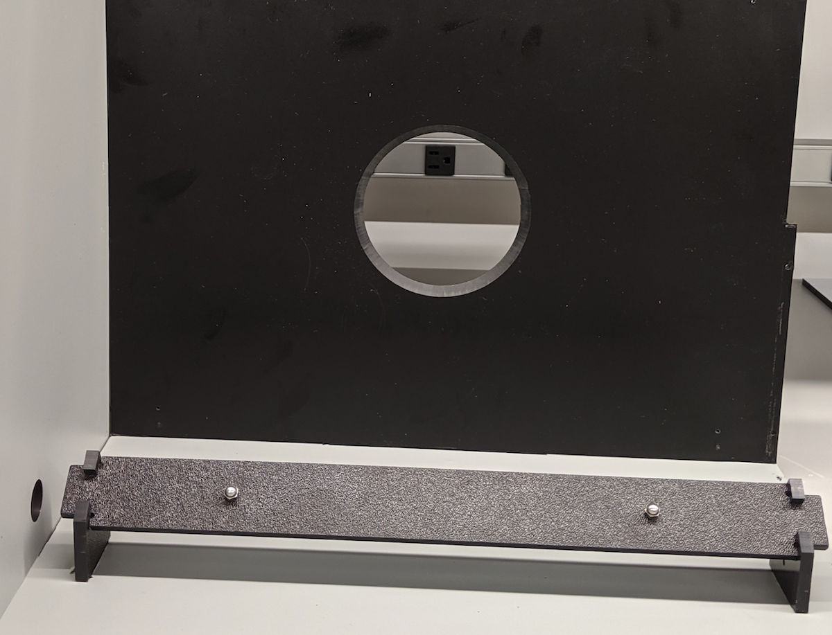
Figure 19. Light placement orientation
Attach the power cord to the power light bar as shown in Figure 20.
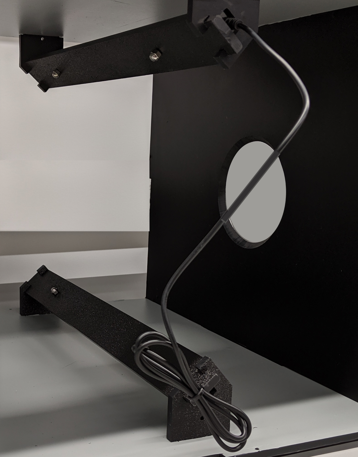
Figure 20. Lighting power cord
Thread the power cord through the hole on the left panel. The power cord has different connectors at each end: the narrower connector attaches to the LED light bar and the larger connector attaches to the power adapter.
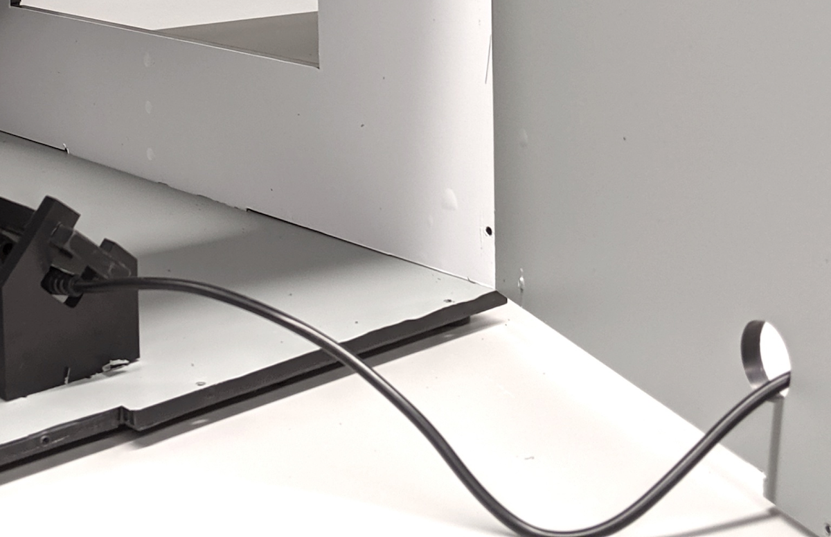
Figure 21. Power cord exiting the test rig on its left side
Wire the top lights to the bottom lights and secure the cable on the left panel.
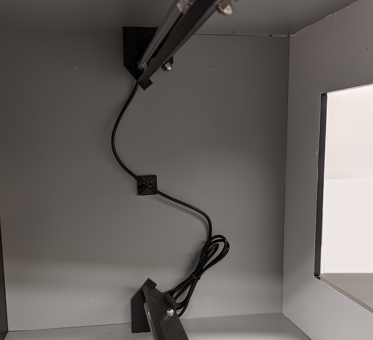
Figure 22. Light cord anchored on the left panel
Step 7: Assemble side panels, tablet mount, and handles
To assemble the ITS-in-a-box side panels, tablet mount, and handles with screws:
Assemble all the sides of the panels and tape them together as shown in Figure 23.
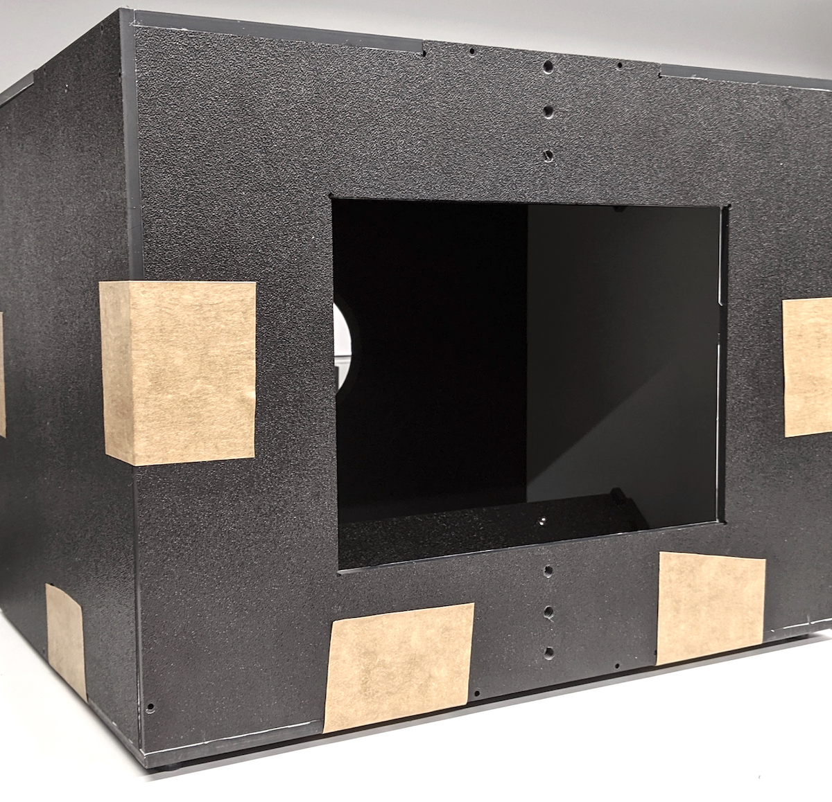
Figure 23. ITS-in-a-box taped together for assembly
Use a power drill to create pilot holes based on the existing holes. Make sure that the pilot holes are big enough for 4-40 screws so that the ABS plastic doesn't crack when inserting the screws.
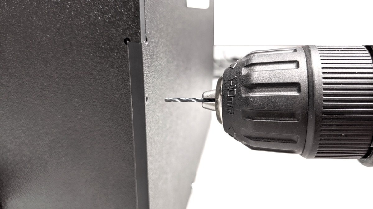
Figure 24. Drilling pilot holes for 4-40 screws
Screw all the panels together using 4-40 self-tapping screws.
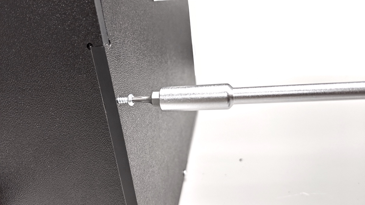
Figure 25. 4-40 screws for assembling panels
Gather the handle parts shown in Figure 26.
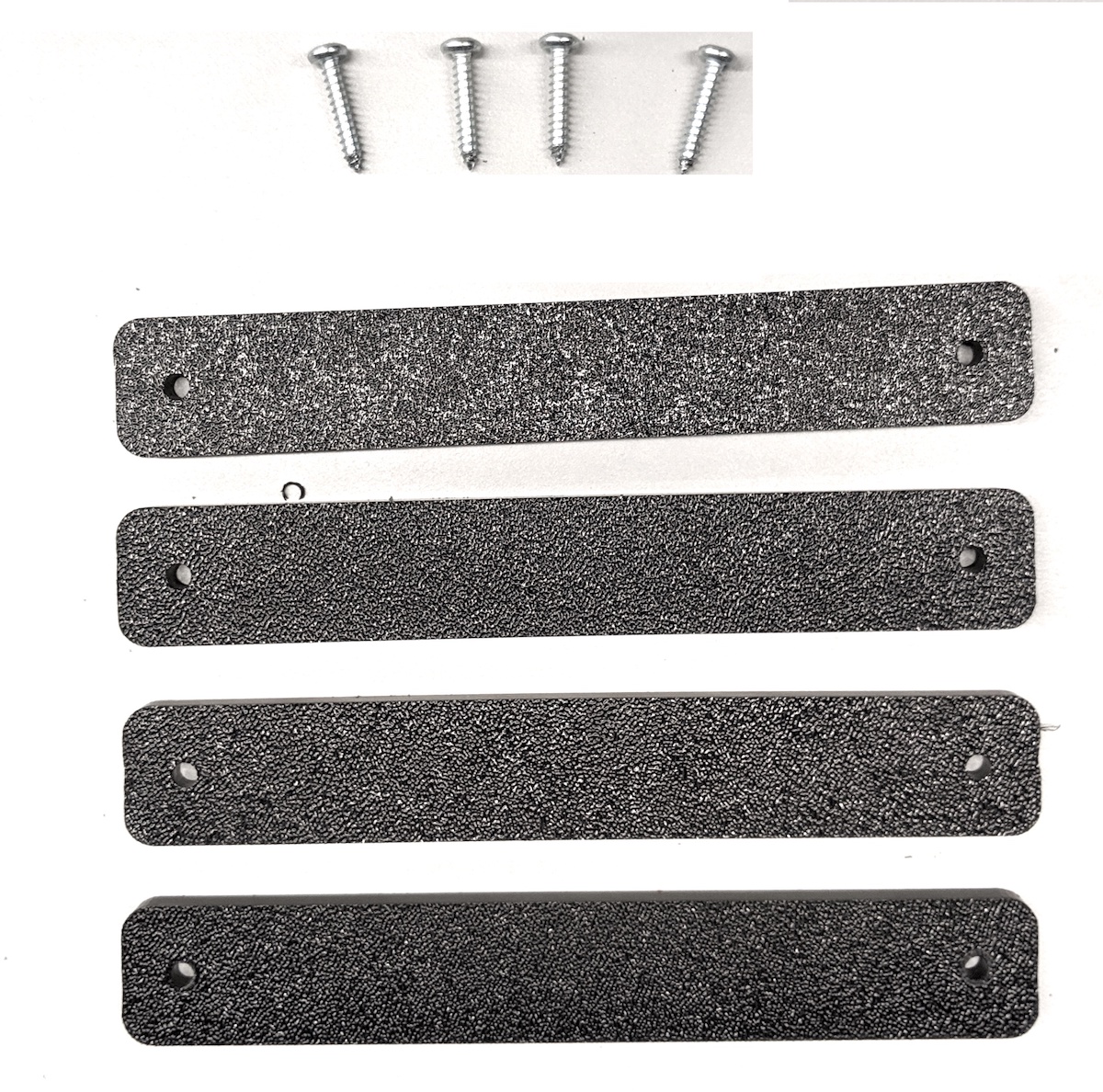
Figure 26. Handle parts
Hardware includes four rectangular plastic pieces and four 6-32 screws.
Assemble the handles as shown in Figure 27.
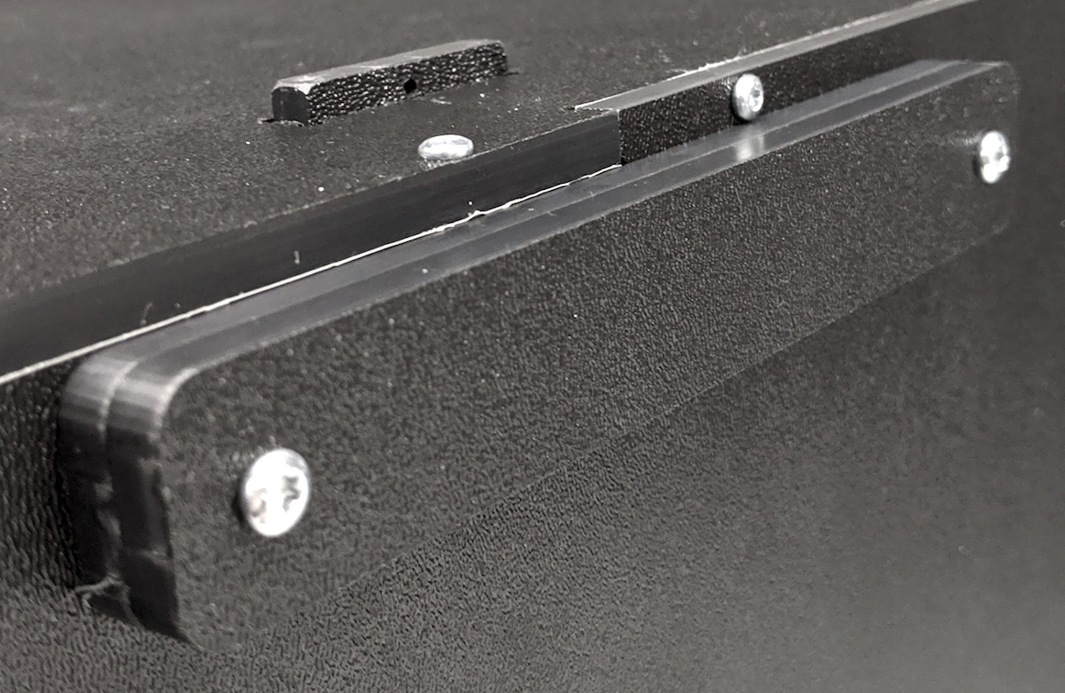
Figure 27. Assembled handle
Step 8: Final assembly and setup
To perform final assembly of the ITS-in-a-box:
Attach the tablet mount to the back panel and adjust the height according to tablet size.
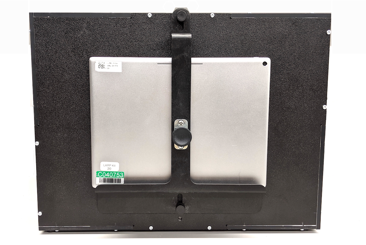
Figure 28. Tablet in the tablet mount on the back of the box
Attach the square aperture panel without phone mounts to the front of the box with 4-40 screws as shown in Figure 29.
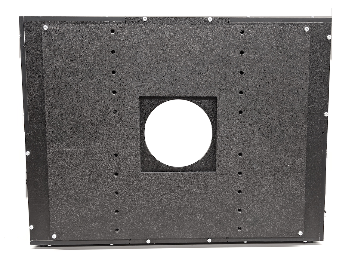
Figure 29. Assembled front phone panel
Insert the 10x10 cm gator board aperture to fit the DUT's camera aperture.
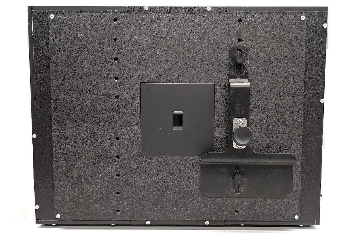
Figure 30. ITS-in-a-box with gator board aperture installed
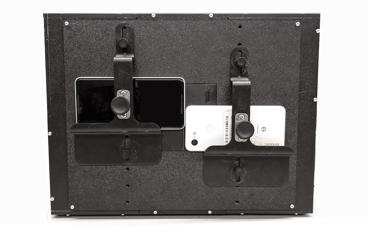
Install the phone by aligning the camera with the aperture opening. Check the alignment through the tablet opening.
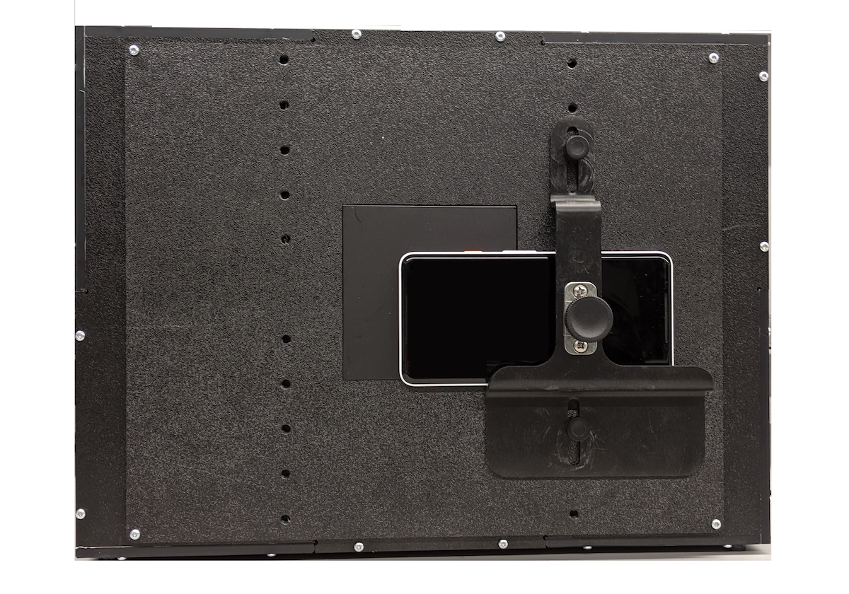
Figure 31. ITS-in-a-box with one phone installed
Cut apertures for the cameras. You can cut a single aperture (for testing a single phone) or two apertures (for testing two phones). Apertures for the Pixel and Pixel XL front and rear cameras are shown in Figure 31. The front camera has a circular aperture because there's no flash or laser, while the rear camera has a rectangular aperture that allows the flash and laser to operate without being blocked.
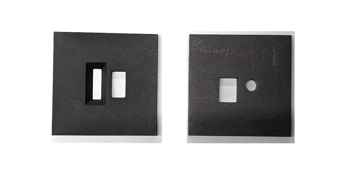
Figure 32. Sample apertures for both front and rear cameras
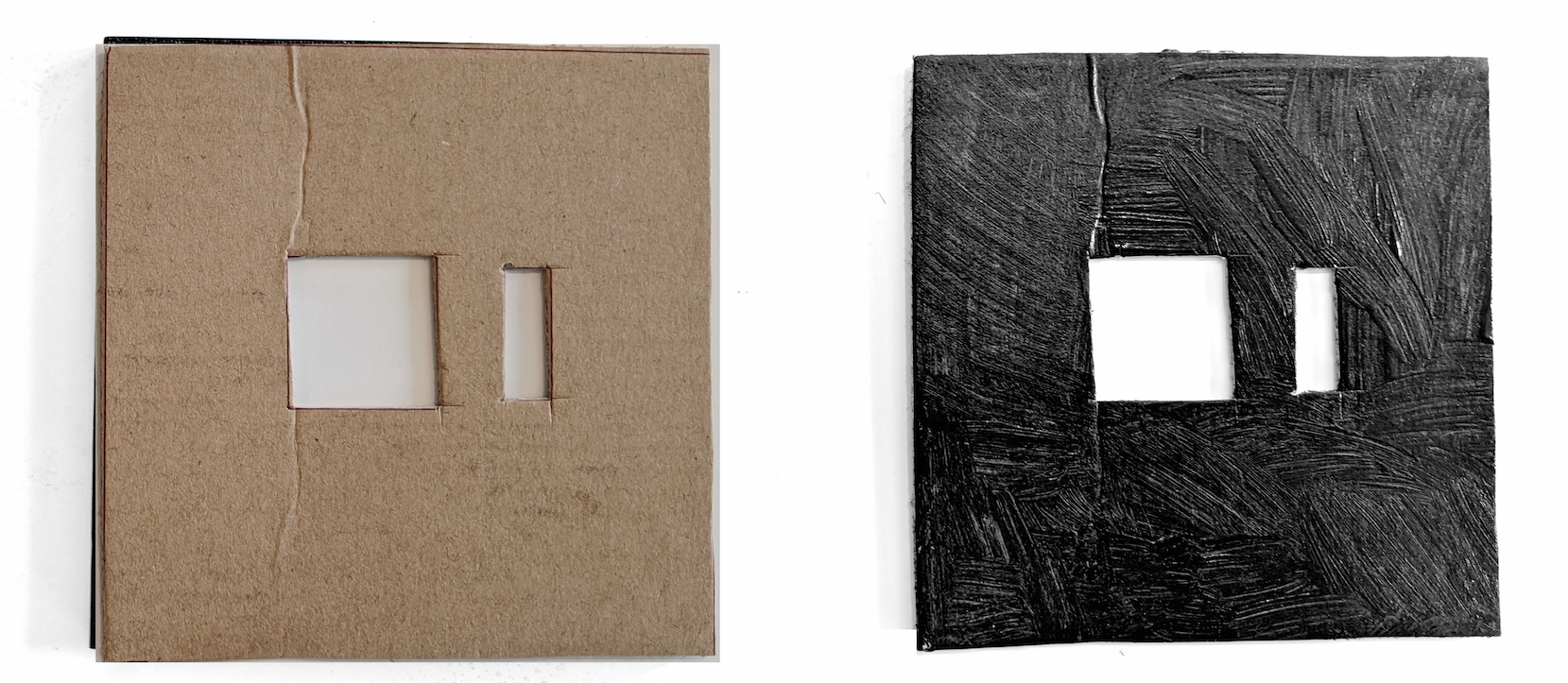
Alternatively, you can also cut apertures out of cardboard and paint it black using markers, spray paint, or acrylic as shown in Figure 33.
Figure 33. Sample cardboard apertures for both front and rear cameras
Using a digital lux tester, test the lux of the LED lights. The YF-1065 by Contempo View is used in this example.
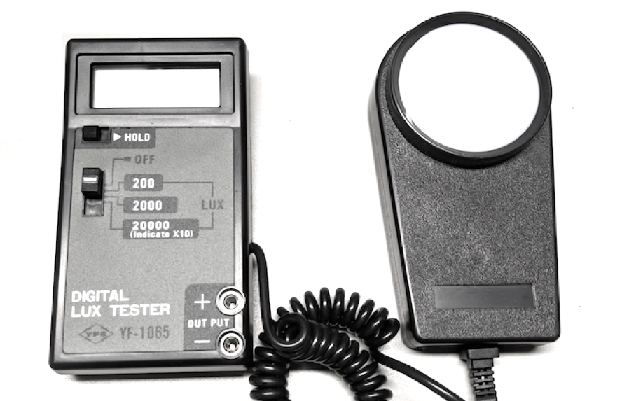
Figure 34. YF-1065 by Contempo Views
Place the light meter on the tablet side and turn it to 2000 lux to measure the light. The lux level should be around 100–300 lux. Anything significantly lower is too dim for the test and can lead to test failures.
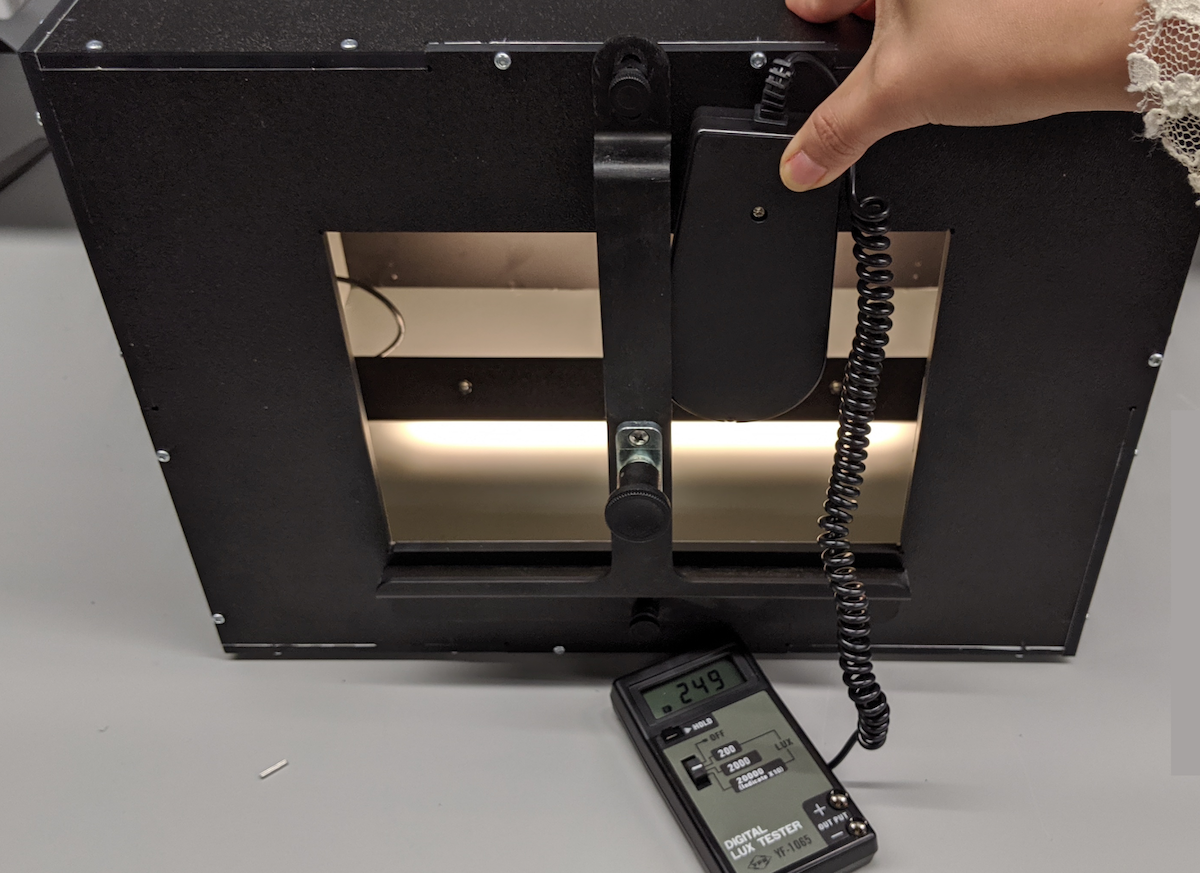
Figure 35. Lux meter measuring light from the back with tablet mount
Follow the appropriate step depending on the lux value measured:
- If the light is at the correct level, screw the front and back plates into place.
- If the light is at the incorrect level, check that the LED and power supply part number are correct.
Things to look out for
The following are examples of common manufacturing errors that can render tests flaky.
Back panel with tablet holes poked through. This causes the
find_circletest to fail because of the extra circles created by the screw holes.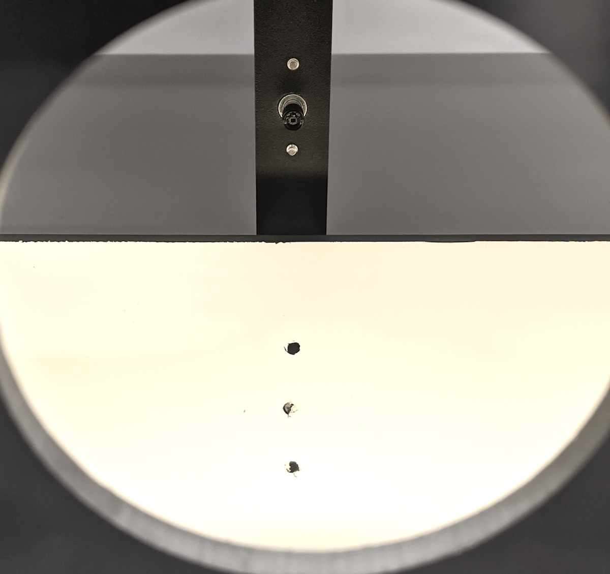
Figure 36. Back panel with holes poked through
Missing dowels. This causes the light baffles to slip out during shipping.
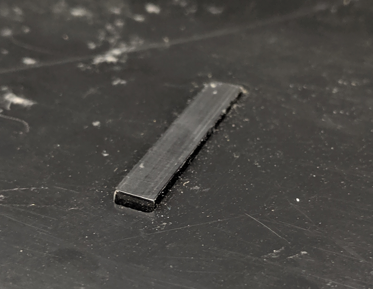
Figure 37. Missing dowel on light baffle
Non-UL-listed power supply. Using a UL-listed power supply ensures that the power supply doesn't break.
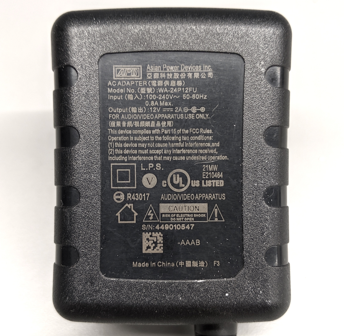
Figure 38. Example of a UL-listed power supply