
This page describes how to assemble the Android 13 controller, which controls movement for a sensor fusion test rig and lighting for ITS-in-a-box. The sensor fusion test is part of the Camera Image Test Suite (Camera ITS) in the Compatibility Test Suite (CTS). The Android 13 controller enables automation by controlling rig lighting and servo motor for tests scenes that require rotation and lighting control.
Android 13 controller overview
ITS-in-a-box provides a consistent testing environment with a fixed distance between the test tablet and test phone, in addition to consistent lighting without an external light source. The Android 13 controller automates both servo control and lighting control, and eliminates the need to manually rotate the DUT for sensor fusion scene tests and to manually toggle lights on and off for lighting-controlled tests.
Servo and lighting control in test rigs
The sensor fusion test rig provides a fixed motion of the phone for reproducible testing. The phone is rotated in front of a checkerboard target to allow image capture with the phone at various positions. For test_sensor_fusion, the servo rotates the phone around the camera center of axis 90 degrees and back in about 2 seconds. For test_video_stabilization, the servo rotates the phone around the camera center of axis 10 degrees and back repeatedly to mimic the phone movement when taking a video while walking. Figure 1 shows two phones moving in a sensor fusion test rig. Figure 2 shows one phone moving in a sensor fusion test rig.
Figure 1. Phone movement in test rig for test_sensor_fusion
Figure 2. Phone movement in test rig for test_video_stabilization
Servo motor control
The analog servo motors in the test rig are positional servos controlled using pulse-width modulation (PWM). A typical positional control example is shown in Figure 3. The control signal has a period of 20 ms. Changing the pulse width to the minimum width moves the motor to the neutral position and changing the pulse width to the maximum width moves the motor 180 degrees clockwise.
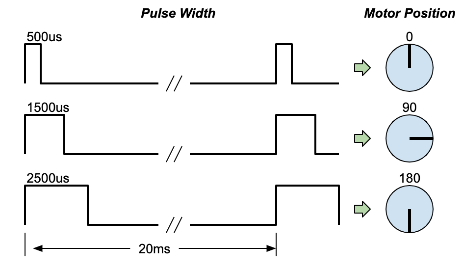
Figure 3. Typical servo control description
Lighting control
To control the servo motor motion and lights using a host computer, the sensor fusion test rig requires a USB connection. The Android 13 controller uses a USB-connected Arduino UNO R3 board with a custom routing board (or shield) mounted on top. The Android 13 controller can control up to three sensor fusion rigs rotator servos, and up to three ITS- in-a-box lighting systems or one sensor fusion rig from a single host computer.
The revision 3.0 Android 13 controller lets users disable auto-reset when the Arduino serial port is opened through USB. The auto-reset function is enabled when the controller is plugged into another host or being used for other test cases. Users can enable or disable auto-reset using a physical switch on the controller.
The Android 13 controller can work with any Camera ITS-in-a-box. The Android 13 controller can be connected to any Camera ITS-in-a-box (RFoV, WFoV, Modular) or Sensor Fusion box to conduct lighting-controlled tests. From Android 15, all lighting-controlled tests are included in scene_flash and can be run using the sensor fusion box, except scene_low_light, which requires a tablet for chart display and must be run using Camera ITS-in-a-box.
For tests in scene_flash and scene_low_light, a dark environment with lights turned off is required to trigger the auto flash function on test phones. Figure 4 shows the lights in ITS-in-a-box being turned off and on by the Android 13 controller.
Figure 4. Lights turned off and on for test_auto_flash
Revision history
The following table describes the revision history of the Android 13 controller and includes download links to each version of the production files.
| Date | Revision | Production file download | Change log |
|---|---|---|---|
| August 2024 | 3.0 |
|
|
| December 2022 | 2.2 |
|
|
| March 2022 | 1 |
|
Android 13 controller setup
This section describes how to set up an Android 13 controller.
Required components
You can purchase the Android 13 controller through one of our qualified vendors or you can build the controller on your own. The production file consists of a PCB Gerber file, the PCB bill of materials (BOM), PCB placement information, and an enclosure STEP file. To download the production file, see the table in Revision history.
If you're building your own controller, you must have an Arduino UNO R3 board. If purchasing the controller through a qualified vendor, the Arduino is included.
The Android 13 controller enclosure is an optional but recommended component that protects the controller and blocks off unused USB ports to prevent setup errors. For details about pricing and options for the controller, contact a qualified vendor.
Setup procedure
To set up the Android 13 controller, follow these steps:
Connect 12V (for lighting) and 5V (for servo) adapters to the appropriate power jacks (Figure 5).
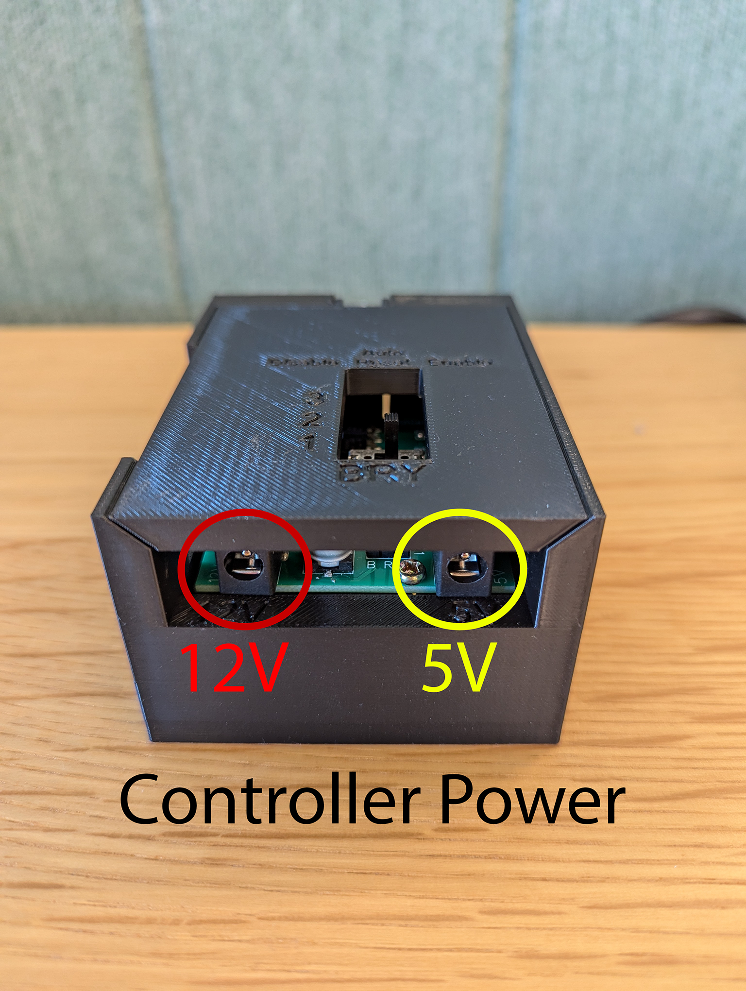
Figure 5. Power adapter location
Connect your ITS-in-a-box or Sensor Fusion box lights to one of the lighting channel output jacks (Figure 6). Depending on the lighting power's barrel use, use an adapter as required (Figure 7).
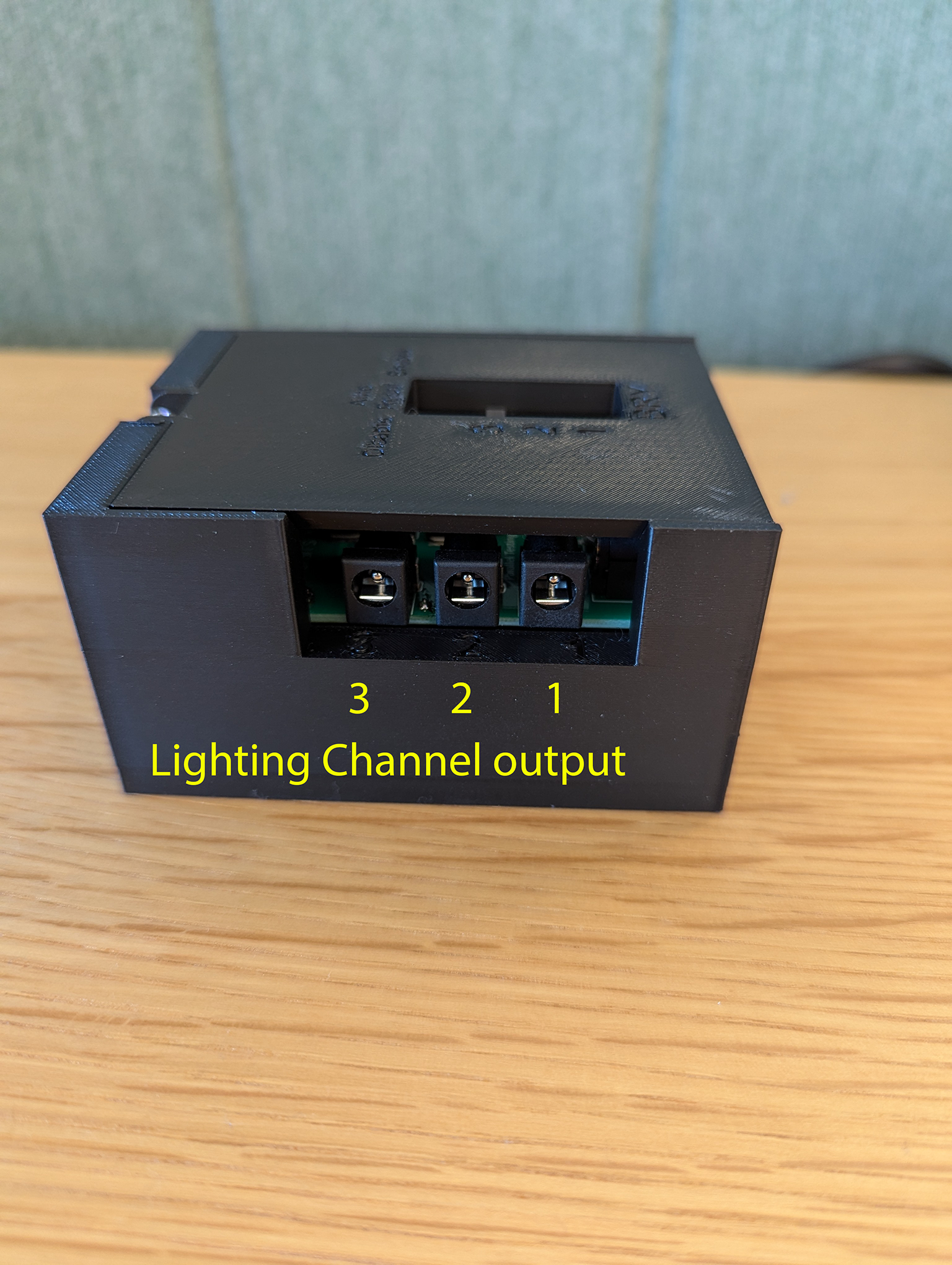
Figure 6. Lighting channels output location
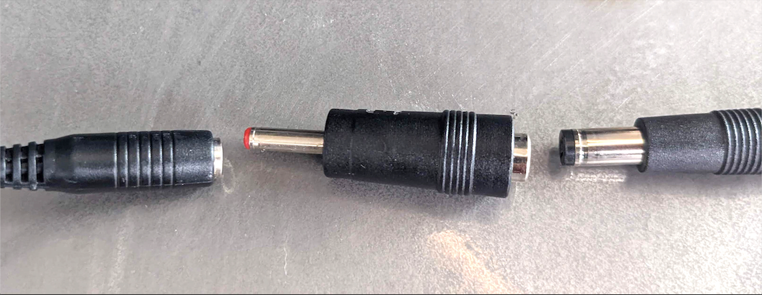
Figure 7. Adapter connecting lighting power to controller
To set up for the sensor_fusion scenes, connect the servo to one of the servo channel connection headers.
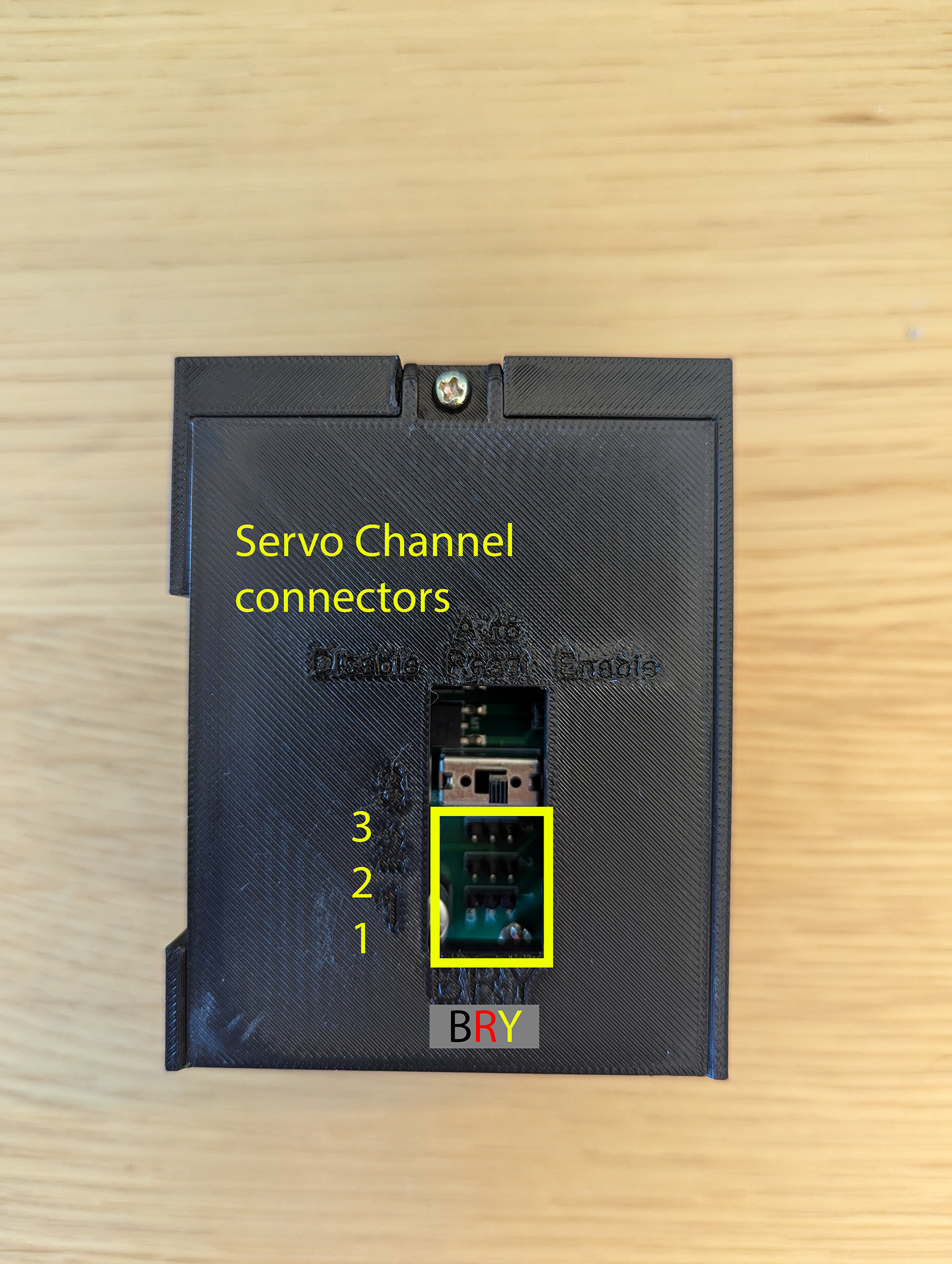
Figure 8. Servo connection location
For revision 3.0 controllers, when connecting the controller to a new host the auto reset switch must be set to
Enable.For revision 3.0, the controller includes an auto reset switch that can be enabled or disabled. When testing, we recommend setting the auto reset switch to
Disableto prevent all lights from going out momentarily at the beginning of each test asits_base_testestablishes communication with the Arduino controller. This is critical when running parallel testing (ITS running simultaneously with the test rig lighting system connected to the same controller).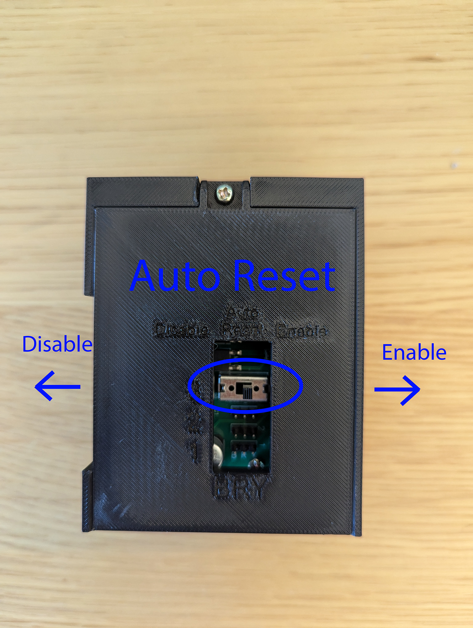
Figure 9. Auto reset switch
Connect the controller to the host with a USB-A cable.
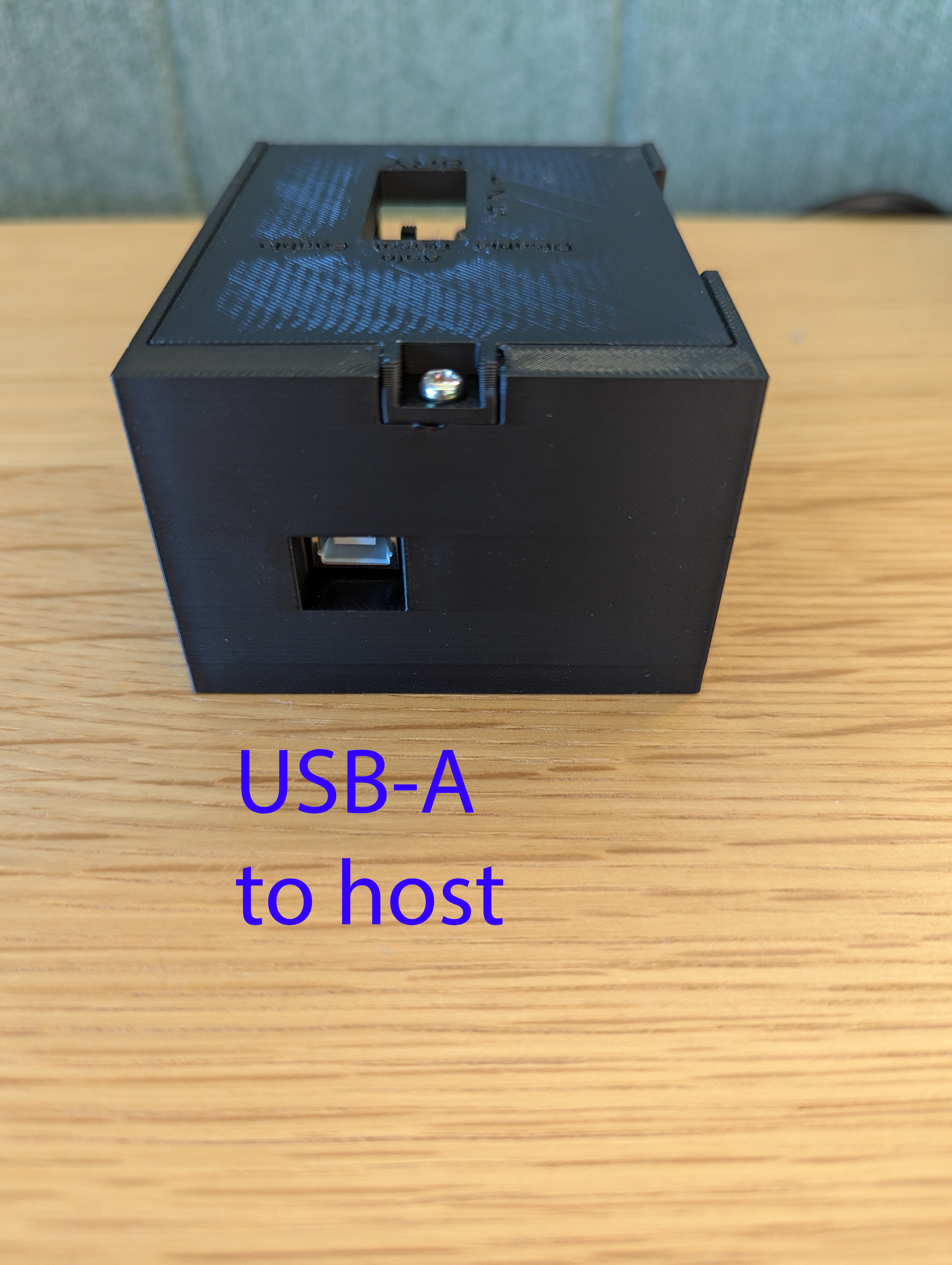
Figure 10. USB-A connection port to host
Figure 11 shows an example of a completed Android 13 controller setup for one lighting system and servo.
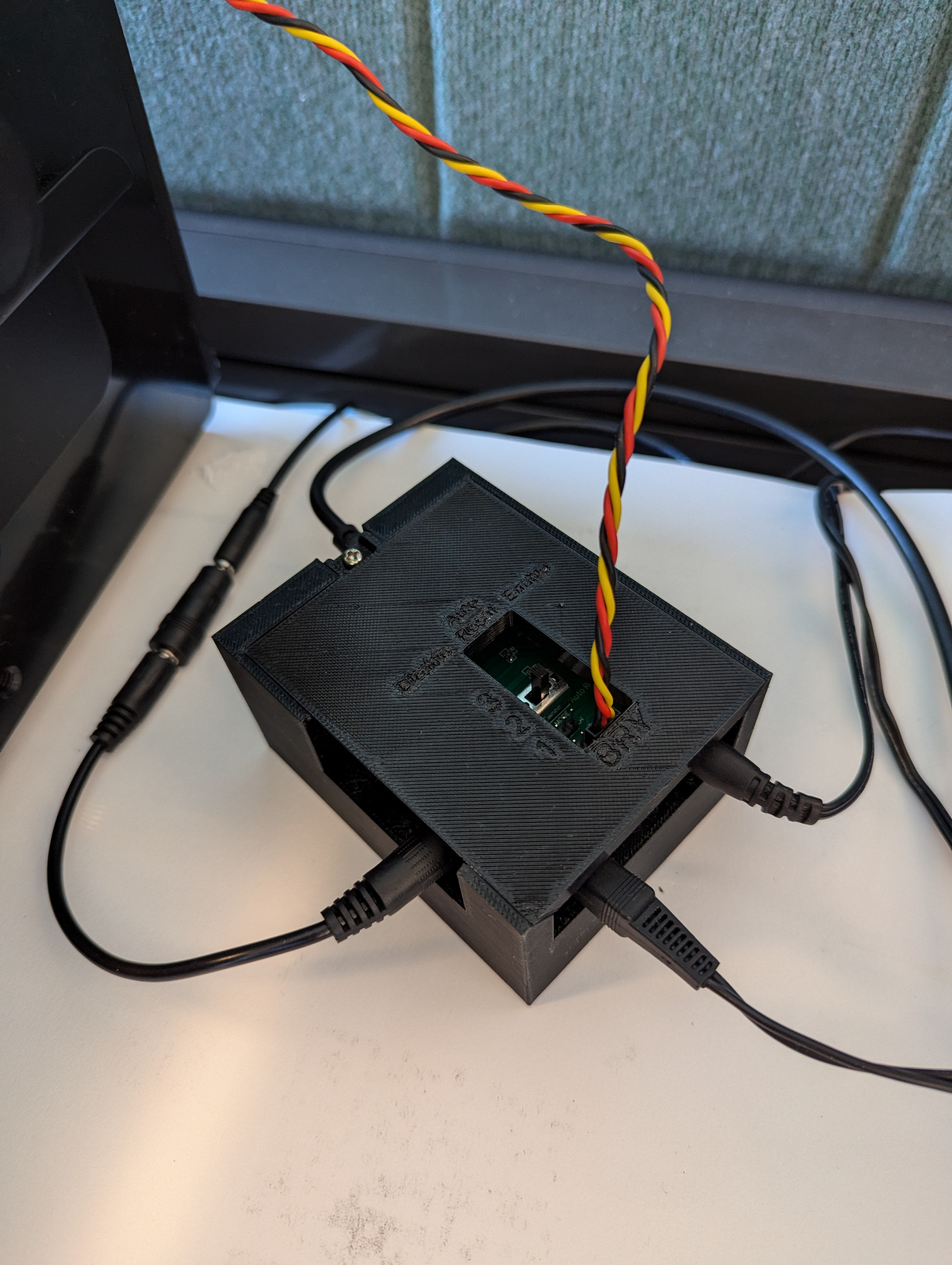
Figure 11. Completed Android 13 controller setup
Software control from host
Micro-code can be downloaded to the UNO to assign the PWM pins to the motor
signals and define the pulse-width ranges for different angles. The micro-code
for servo rotation control of the six HS-755MB motors is included in
Other resources. That section also includes a link to a
simple program called rotator.py, which rotates the servos.
Using the Android 13 controller
Camera ITS usage:
python tools/run_all_tests.py device=device_id camera=0 rot_rig=arduino:1 scenes=sensor_fusion
With included test script:
python rotator.py --ch 1 --dir ON --debug