
The Android audio system can play and record audio signals through a wide variety of routes, peripherals, and configurations. Manually testing basic audio capabilities on a complex system is slow and tedious. To address this, CTS Verifier implements several data paths tests, which automatically validate basic audio capability across a large number of routes and configurations.
There are three areas of audio data paths tests:
- Analog headset jack path, if available
- On-device speaker and microphone path
- USB audio peripheral (USB headset and USB audio interface) path
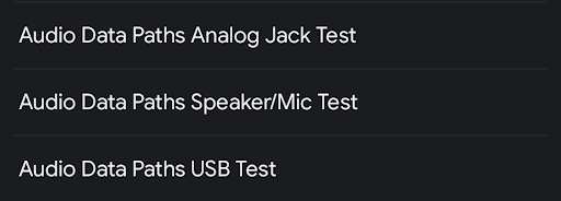
Figure 1. Audio data paths test lists panel.
Common elements
Before a test is run, the test panel displays the following:
A list of audio attributes, and whether they're supported or not by the DUT. This list determines which data path and attribute specifications can be run. For example, data path or attributes for MMAP paths aren't run on devices that don't support MMAP.
- Mic - The DUT contains a built-in microphone.
- Speaker - The DUT contains a built-in speaker.
- MMAP - The DUT supports MMAP audio mode.
- MMAP Exclusive - The DUT supports MMAP Exclusive audio mode.
A selection of audio APIs
- Java API - Playback and recording is done with the Java audio API.
- Native API - Playback and recording is done with the native audio API.
A Calibrate Audio button to invoke the Audio Loopback Calibration Panel, to set the signal level before running the tests
Test process buttons:
Start - Starts the test sequence. Any testable, failed data paths or configurations are tested.
Cancel - Stops the current test sequence.
Clear Results - Clears the result code for all data paths. This option can be used to run the complete test sequence after previous tests, which might have failed.
A signal display panel (oscilloscope). This panel shows the signal while the tests are being run. A displayed signal that doesn't show a clean, high-amplitude sine wave is indicative of a problematic data path.
The number of samples displayed changes depending on the data path or configuration, so it's normal for different number of cycles of the sine wave to appear.
The list of data path or configuration specifications under test. This lists the possible configurations to run on the audio I/O peripheral, associated with the selected data paths test. The data paths or configurations that are valid for the DUT and available peripherals that are connected to the DUT are shown with an asterisk, along with the status of the test (PASS, FAIL or NOT TESTED).
While the test is running, the current data path or configuration is indicated by >> << surrounding the specification.
See the following figure for more information:
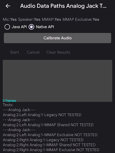
Figure 2. Audio data paths test panel.
Audio data paths analog jack test
The audio data paths analog jack test tests basic audio capability through the analog headset path. If the DUT doesn't have an analog headset jack, a PASS is automatically granted.
Required peripherals
See Audio loopback plug for more information.
The following figures show the screens for the audio data paths audio jack test before and after completion:
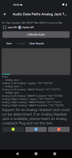
Figure 3. Audio data path analog jack test ready to run.
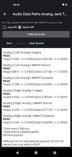
Figure 4. Audio data path analog jack test after successful completion.
Do the following to run the audio data paths analog jack test:
- Insert the loopback plug into the analog headset jack on the DUT. The tests list is updated to show the valid data paths.
- Use the Audio Loopback Calibration panel to set an appropriate signal level.
Press Start. The test steps through each data path or configuration and measures the signal magnitude and jitter to determine if the data path or configuration is operating correctly.
You can monitor the signal display to determine visually if the signal looks correct. The test displays the result for each data path or configuration after it runs.
When the test sequence is completed, the signal display and data paths or configuration list is replaced with a panel showing the results. Failures for portions of the failed test (such as magnitude or jitter) are displayed in red text along with the unmet threshold or requirement.
Click PASS or FAIL, as appropriate.
Audio data paths speaker and microphone test
The audio data paths speaker and microphone test tests basic audio capability through the on-device speaker and microphone path.
Required peripherals
No external peripherals are required for this test.
The following figures show the screens for the audio data paths speaker and mic test before and after completion. Errors are marked in red:
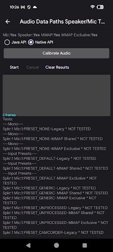
Figure 5. Audio data path speaker and microphone test ready to run.
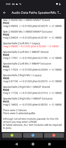
Figure 6. Audio data path speaker and microphone test after successful completion.
To run the audio data paths speaker and microphone test:
- Place the DUT flat on a desk or table in a quiet environment. Loud noises while the test is running can interfere with the analysis of the captured audio.
- Use the Audio Loopback Calibration panel to set an appropriate signal level.
Press Start. The test steps through each data path or configuration measuring signal magnitude and jitter to determine if the data path or configuration is operating correctly.
You can monitor the signal display to visually determine if the signal looks correct. The test displays the result for each data path or configuration as the test sequence proceeds.
When the test sequence is completed, the signal display and data paths or configuration list is replaced with a panel showing the results. Failures for portions of the failed test (such as magnitude or jitter) are displayed in red text along with the unmet threshold or requirement.
Click PASS or FAIL, as appropriate.
Audio data paths USB test
The audio data paths USB test tests basic audio capability through the USB audio peripheral (USB headset and USB audio interface) path.
Required peripherals
See USB audio interface for more information.
The following figures show the screens for the audio data paths USB test before and after completion:
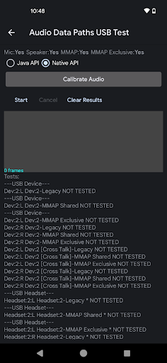
Figure 7. Audio data path USB test ready to run.
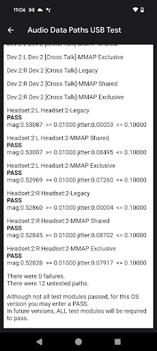
Figure 8. Audio data path USB test after successful completion.
To run the audio data paths USB test:
Connect the USB audio peripheral to the DUT. The test sequence must be run separately for each of the following cases:
- A USB-to-analog headset adapter with a loopback plug inserted
- A USB audio interface with patch cables connecting the outputs to the inputs
Use the Audio Loopback Calibration panel to set an appropriate signal level.
Press Start. The test steps through each data path or configuration measuring signal magnitude and jitter to determine if the data path or configuration is operating correctly.
You can monitor the signal display to visually determine if the signal looks correct. The test displays the result for each data path or configuration as the test sequence proceeds.
When the test sequence is completed, the signal display and data paths or configuration list is replaced with a panel showing the results. Failures for portions of the failed test (such as magnitude or jitter) are displayed in red text along with the unmet threshold or requirement.
Repeat steps 1 through 3 for the untested USB peripheral.
Click PASS or FAIL, as appropriate.
Interpret the test results
For each configuration, a sine wave is generated on the output and the input is captured. The test tries to detect a sine wave at the input with the same frequency as the generated tone.
For each configuration, magnitude and jitter measurements are displayed, defined as follows:
Magnitude: The magnitude (or level) of the input sine wave is analyzed in a manner similar to an Fast Fourier Transform (FFT). If the magnitude is too low, that might mean the signal is blocked or that a specific channel isn't functioning. It might also mean the output volume or the input gain is too low. The magnitude must be at a certain level to pass.
Jitter: The phase of the captured sine wave is also measured relative to the generated signal. A constant relative phase indicates that the captured signal corresponds to the generated signal. If the relative phase is changing, either the generated signal is corrupted or some other signal such as noise is being captured. The changes in relative phase are called jitter.
If the input is just capturing a loud noise then the magnitude might be high as the noise can contain all sine wave frequencies. In this case, the analyzer can't lock onto the generated sine wave, exhibiting high jitter.
The following table interprets the result for various combinations of the magnitude and jitter measurements:
| Magnitude | Jitter | Result | Interpretation |
|---|---|---|---|
| High | Low | PASS | A clean version of the output sine wave is captured. |
| High | High | FAIL | A loud noise or a very corrupt signal is captured. |
| Low | Low | FAIL | A clean signal is recorded at too low a level. |
| Low | High | FAIL | A quiet signal that is corrupted or noisy is captured. |
If the CTS Verifier test is failing, run the Data Paths test in the latest version of OboeTester. The OboeTester tool prints a detailed report and can help you debug the problem.