
Camera Image Test Suite (ITS) is a framework for running tests on images produced by an Android camera. The general goal of each test in ITS is to configure the camera in a specific manner, capture one or more shots, and examine the shots to see if they contain the expected image data. Many of the tests require the camera to be pointed at a specific target chart or be illuminated at a specific intensity.
ITS is located in the CTS Verifier test harness in
cts/apps/CameraITS.
Devices must pass the ITS tests corresponding to the supported features
advertised by the camera framework for third party apps as a subset of CTS.
Setup
To run ITS tests, the following must be set up:
- A device under test (DUT)
- A host machine (for example, a Linux desktop or laptop)
- A scene that the camera photographs
Device under test (DUT) setup
To set up a DUT, follow these steps:
- Connect the DUT to a host machine over USB.
- Configure developer options on the DUT:
- Turn ON Stay awake and USB debugging.
- Turn OFF Automatic system updates and Verify apps over USB.
- Grant permissions for the host to access the DUT over ADB.
Install the CTS Verifier app (
CtsVerifier.apk) onto the device. For more information, see Using CTS Verifier.extract root/out/host/linux-x86/cts-verfier/android-cts-verifier.zipcd android-cts-verifieradb install -r -g CtsVerifier.apkOn the DUT, launch the default camera app and clear all the windows that appear upon launch to avoid interference during testing.
Host setup
ITS requires the host machine to be connected to the DUT through USB, be able to use ADB for device control and communication, and have the required software installed.
To set up your host machine, ensure the following software is installed.
Android SDK Platform Tools
The Android SDK Platform tools must be installed and ADB must be in the executable path of the shell or terminal that is running on the host machine. For the public released version of the Android SDK Platform tools, see SDK Platform Tools release notes.
Python
Python must be installed on the host machine. We recommend using a bundled Python distribution to ensure support for compatible versions. For details on which Python and package versions to install for a specific release, see the Camera ITS release notes for the corresponding release.
Mobly
For Android 12 and higher, install the Mobly test
framework. Mobly lets you set up a DUT and chart tablet in the
its_base_test class. To install the Mobly test framework, run:
pip install moblyEnvironment setup
To set up the test environment, run:
cd CameraITSsource build/envsetup.sh
This command checks the Python installation, sets up the PYTHONPATH
environment variable, and runs unit tests on the utils/*.py modules. If no
errors are printed to the terminal, the environment is ready to run the ITS
tests.
Scene setup
To set up the scenes, we recommend using the Camera ITS-in-a-box setup for ease in automation, reliability, and efficiency in testing. The ITS-in-a-box test rigs support all the lighting, centering, and chart changing requirements for ITS. Also, ITS-in-a-box is required for camera extensions testing.
For manual testing, ensure the following:
- The DUT is on a tripod
- The DUT is pointed at the correct scene for each test. (The ITS test script provide prompts to change the scene setup before starting tests in a new scene.)
- The DUT is connected to the host machine over USB.
- The DUT doesn't move during the test run.
- The scene is illuminated with a steady, non-fluctuating light source. (Don't use a fluorescent light because this introduces flicker.)
The ITS test script displays a prompt asking the user to change the scene setup before starting tests in a new scene.
The phone orientation must be set so that the camera takes images with no rotation. The easiest way to check this is with the face scenes in scene2. Most phones have the phone in landscape orientation with the phone rotated counter-clockwise for the rear camera and rotated clockwise for the front camera.
To check the DUT and chart alignment, run tools/check_alignment.py to output
the x,y coordinates for the center of the chart versus the center of the image,
and annotate a captured image with the two centers for optimum alignment.
Configuration files
Using the Mobly framework, you must create a config.yml configuration file to
define the Mobly testbed. The following are examples for different use cases.
Tablet-based scenes config.yml file
The following is an example config.yml file for tablet-based scenes. For
tablet-based testing, the keyword TABLET must be in the testbed name. During
initialization, the Mobly test runner initializes the parameters in the file
and passes them to the individual tests.
TestBeds:
  - Name: TEST_BED_TABLET_SCENES
    # Test configuration for scenes[0:4, 6, _change]
    Controllers:
        AndroidDevice:
          - serial: 8A9X0NS5Z
            label: dut
          - serial: 5B16001229
            label: tablet

    TestParams:
      brightness: 192
      chart_distance: 22.0
      debug_mode: "False"  # "True" or "False"; quotes needed
      lighting_cntl: <controller-type>  # "arduino" or "None"; quotes needed
      lighting_ch: <controller-channel>
      camera: 0
      foldable_device: "False". # set "True" if testing foldable
      scene: <scene-name>  # if <scene-name> runs all scenes
To invoke the test bed, run tools/run_all_tests.py. If there are no command
line values specifying cameras or scenes, the test is run with the config.yml
file values. If there are command line values for cameras or scenes, these
override the values in the TestParams section of the config.yml file.
For example:
python tools/run_all_tests.pypython tools/run_all_tests.py camera=1python tools/run_all_tests.py scenes=2,1,0python tools/run_all_tests.py camera=0 scenes=scene_telepython tools/run_all_tests.py camera=0.4 scenes=4,scene6_tele
chart_scaling parameter
In Android 17 and higher, the chart_scaling parameter
is included in config.yml for TEST_BED_TABLET_SCENES. This parameter
addresses chart scaling issues for tele camera devices with a wider field of
view (FoV), preventing scene cropping and enforcing proper device focus during
testing.
Supported values for chart_scaling are 1, 0.33, 0.5, or 0.67, with
None as the default. This approach lets devices use an optimal scaling factor
tailored to their specific requirements, maintaining functional testing across
all devices.
If chart_scaling is set to None, the tests automatically determine the
scaling factor using chart_scaling_logic. Otherwise, the value specified in
config.yml is used, or an error is flagged if the scaling is unavailable.
The following is a sample config.yml with the chart_scaling parameter
TestBeds:
  -   Name: TEST_BED_TABLET_SCENES  # Need 'tablet' in name for tablet scenes
    # Use TEST_BED_MANUAL for manual testing and remove below lines:
    #     - serial <tablet_id>
    #       label: tablet
    # Test configuration for scenes[0:4, 6]
    Controllers:
        AndroidDevice:
          -   serial: <device-id>  # quotes needed if serial id entirely numeric
            label: dut
          -   serial: <tablet-id>  # quotes needed if serial id entirely numeric
            label: tablet
    TestParams:
      brightness: 192
      chart_distance: 22.0
      debug_mode: "False"  # quotes needed
      lighting_cntl: <controller-type>  # can be arduino or "None"
      lighting_ch: <controller-channel>
      camera: <camera-id>
      scene: <scene-name>  # if <scene-name> runs all scenes
      foldable_device: "False"  # "True" if testing foldable device
      chart_scaling: "None"  # use the values available for scene to be tested
      resultstore_upload: "False"  # "True" if results should be uploaded to ResultStore
Test-side adjustments are required to enable Camera ITS chart scaling capabilities. If a test you are using doesn't support this, file a bug.
The following is a sample test side change with the chart_scaling parameter.
# load chart for scene
      its_session_utils.load_scene(
          cam, props, self.scene, self.tablet, self.chart_distance,
          chart_scaling=self.chart_scaling)
sensor_fusion scene config.yml file
The following is an example config_yml file for sensor_fusion tests.
For sensor_fusion testing, the keyword SENSOR_FUSION must be in the testbed
name. Android 13 and higher support only the Arduino
controller for sensor fusion because of preview and video stabilization testing.
Android 12 supports Arduino and Canakit controllers.
Testbeds
  - Name: TEST_BED_SENSOR_FUSION
    # Test configuration for sensor_fusion/test_sensor_fusion.py
    Controllers:
        AndroidDevice:
          - serial: 8A9X0NS5Z
            label: dut

    TestParams:
      fps: 30
      img_size: 640,480
      test_length: 7
      debug_mode: "False"
      chart_distance: 25
      rotator_cntl: arduino
      rotator_ch: 1
      camera: 0
To run sensor_fusion tests with the
sensor fusion box, run:
python tools/run_all_tests.py scenes=sensor_fusionpython tools/run_all_tests.py scenes=sensor_fusion camera=0python tools/run_all_tests.py scenes=scene_flash,feature_combinationpython tools/run_all_tests.py scenes=checkerboard camera=1
Multiple testbeds config.yml file
The following is an example config.yml file with multiple testbeds, a
tablet testbed and a sensor_fusion testbed. The correct testbed is determined
by the scenes tested.
Testbeds
  - Name: TEST_BED_TABLET_SCENES
    # Test configuration for scenes[0:4, 6, _change]
    Controllers:
        AndroidDevice:
          - serial: 8A9X0NS5Z
            label: dut
          - serial: 5B16001229
            label: tablet

    TestParams:
      brightness: 192
      chart_distance: 22.0
      debug_mode: "False"
      chart_loc_arg: ""
      camera: 0
      scene: <scene-name>           # if <scene-name> runs all scenes

  - Name: TEST_BED_SENSOR_FUSION
    # Test configuration for sensor_fusion/test_sensor_fusion.py
    Controllers:
        AndroidDevice:
          - serial: 8A9X0NS5Z
            label: dut

    TestParams:
      fps: 30
      img_size: 640,480
      test_length: 7
      debug_mode: "False"
      chart_distance: 25
      rotator_cntl: arduino         # cntl can be arduino or canakit
      rotator_ch: 1
      camera: 0
Manual testing config.yml file
The following is an example config.yml file for manual testing. Android 14
and higher supports manual testing for all tests except for the
scene_extensions
tests. For manual testing, the keyword MANUAL must be in the testbed name.
Also, the AndroidDevice section can't include a serial or label section for
a tablet.
TestBeds:
  - Name: TEST_BED_MANUAL
    Controllers:
        AndroidDevice:
          - serial: 8A9X0NS5Z
            label: dut

    TestParams:
      debug_mode: "False"
      camera: 0
      scene: 1
Gen2 rig testing config.yml file
The following is an example config.yml file of a TEST_BED_GEN2 testbed.
Use this testbed for scene_ip tests, which use a
Gen2 rig.
The following example shows the testbed parameters when the Gen2 rig is
available and the
scene_ip
tests aren't skipped.
Testbeds
  - Name: TEST_BED_GEN2
    # Test configuration for scene_ip/test_default_jca_ip.py
    Controllers:
        AndroidDevice:
          - serial: <device-id>  # quotes needed if serial id entirely numeric
            label: dut
    TestParams:
      debug_mode: "False"  # quotes are needed here
      chart_distance: 30
      rotator_cntl: gen2_rotator   # gen2 rig specific. "None" if gen2 rig not available
      rotator_ch: 0
      camera: <camera-id>
      foldable_device: "False"  # "True" if testing foldable device
      tablet_device: "False"  # "True" if testing tablet device
      lighting_cntl: gen2_lights  # gen2 rig specific. "None" if gen2 rig not available
      lighting_ch: 1
      scene: scene_ip
The following example shows testbed parameters when the Gen2 rig
isn't available and the scene_ip tests are skipped.
Testbeds
  - Name: TEST_BED_GEN2
    # Test configuration for scene_ip/test_default_jca_ip.py
    Controllers:
        AndroidDevice:
          - serial: <device-id>  # quotes needed if serial id entirely numeric
            label: dut
    TestParams:
      debug_mode: "False"  # quotes are needed here
      chart_distance: 30
      rotator_cntl: "None"   # gen2 rig specific. "None" if gen2 rig not available
      rotator_ch: <controller-channel>
      camera: <camera-id>
      foldable_device: "False"  # "True" if testing foldable device
      tablet_device: "False"  # "True" if testing tablet device
      lighting_cntl: "None"  # gen2 rig specific. "None" if gen2 rig not available
      lighting_ch: <controller-channel>
      scene: scene_ip
To run the scene_ip test, use one of the following commands:
python tests/scene_ip/test_default_jca_ip.py -c config.ymlpython tools/run_all_tests.py camera=<camera-id> scenes=scene_ip
Running ITS tests
This section describes how to run ITS tests.
Invoking tests
After the device, host machine (including environment), and physical scene are set up, run the ITS tests using the following process.
Open the CTS Verifier app. In the tests menu, select Camera ITS Test. For Android 17 and higher, the
sensor_fusionandfeature_combinationtests are in an additional activity named Camera ITS Sensor Fusion Rig Test.From the host machine, run the ITS tests from the
CameraITS/directory. For example, for a device with front and rear cameras, run the following command:python tools/run_all_tests.pyThe script iterates through cameras and test scenes based on the
config.ymlfile. For debugging setups, we recommend running one of thescene2scenes with a single test for fastest turnaround.For manual testing, before starting to run the set of ITS tests on each scene, the script takes a picture of the current scene, saves it as a JPEG, prints the path to the JPEG to the console, and asks the user to confirm if the image is okay. This capture and confirm flow loops until the user confirms the image is okay. The following are the messages in this flow.
Preparing to run ITS on camera 0
Start running ITS on camera:  0
Press Enter after placing camera 0 to frame the test scene:
scene1_1
The scene setup should be: A grey card covering at least the   middle 30% of the scene
Running vendor 3A on device
Capture an image to check the test scene
Capturing 1 frame with 1 format [yuv]
Please check scene setup in /tmp/tmpwBOA7g/0/scene1_1.jpg
Is the image okay for ITS scene1_1? (Y/N)
Each run of the script prints out a log showing either
PASS,FAIL,FAIL*orSKIPfor each ITS test.FAIL*indicates the test failed but because the test isn't yet mandated, the test will report as aPASSto CtsVerifier.SKIPindicates the test was passed because the device didn't advertise the underlying capability being tested. For example, if a device doesn't advertise through the camera interfaces that it supports DNG, tests related to DNG file capture are skipped and counted as aPASS.To acknowledge that the tests have met the test requirements, tap the green check mark button. The Camera ITS Test entry in the CTS Verifier tests menu then becomes green and signifies the phone has passed Camera ITS.
Reducing test time
Camera ITS supports several features to optimize and reduce overall test execution time across devices and scenes.
Sub-camera testing
One of the most effective methods for reducing camera test time, is to expose a single logical camera to third-party apps with the multi-camera API. The multi-camera API defines a logical camera system consisting of a primary camera, generally the wide field-of-view camera, along with physical sub-cameras that operate at different zoom levels, generally the ultra-wide and telephoto cameras. Cameras using the multi-camera API reduce test time significantly compared to exposing cameras individually. While the main logical camera runs the full test suite, sub-cameras run a targeted subset of the overall test suite as shown in the following table:
| Scene | Sub-camera tests |
|---|---|
| scene0 | test_jitter, test_solid_color_test_pattern |
| scene1_1 | test_burst_sameness_manual, test_dng_noise_model, test_exposure, test_linearity |
| scene1_2 | test_raw_exposure, test_raw_sensitivity, test_yuv_plus_raw |
| scene2_a | test_faces, test_num_faces |
| scene3 | test_flip_mirror |
| scene4 | test_aspect_ratio_and_crop |
| sensor_fusion | test_sensor_fusion |
Parallel DUT testing
Devices running Android 14 or higher support parallel
DUT testing. This lets you test DUTs in parallel with multiple rigs to speed
up overall testing. For example, parallel testing lets you test camera 0 in one
rig and camera 1 in another rig at the same time. For Android
17 and higher, because Camera ITS tests are split into
two activities, you can run sensor_fusion and feature_combination
tests on one DUT, and other tests on another DUT in parallel. All testing for parallel
testing sessions is aggregated on the CTS Verifier session on the reference DUT.
You must run parallel testing with Arduino lighting control, as manual lighting
control isn't supported with parallel testing. Make sure that a different
channel on the same Arduino controller controls the lighting for each rig.
The following is a sample config.yml file that defines three testbeds to run
in parallel.
TestBeds:
  - Name: TEST_BED_TABLET_SCENES_INDEX_0
    Controllers:
        AndroidDevice:
          - serial: <device-id-0>
            label: dut
          - serial: <tablet-id-0>
            label: tablet
    TestParams:
      brightness: 192
      chart_distance: 22.0
      debug_mode: "False"
      lighting_cntl: "arduino"
      lighting_ch: <controller-channel-0>
      camera: 0
      scene: <scene-name>  # if <scene-name> left as-is runs all scenes
      foldable_device: "False"

  - Name: TEST_BED_TABLET_SCENES_INDEX_1
    Controllers:
        AndroidDevice:
          - serial: <device-id-1>
            label: dut
          - serial: <tablet-id-1>
            label: tablet
    TestParams:
      brightness: 192
      chart_distance: 22.0
      debug_mode: "False"
      lighting_cntl: "arduino"
      lighting_ch: <controller-channel-1>
      camera: 1
      scene: <scene-name>  # if <scene-name> left as-is runs all scenes
      foldable_device: "False"

  # TEST_BED_SENSOR_FUSION represents testbed index 2
  # Parallel sensor_fusion is currently unsupported due to Arduino requirements
  - Name: TEST_BED_SENSOR_FUSION
    # Test configuration for sensor_fusion
    Controllers:
        AndroidDevice:
          - serial: <device-id>
            label: dut
    TestParams:
      fps: 30
      img_size: 640,480
      test_length: 7
      debug_mode: "False"
      chart_distance: 25
      rotator_cntl: "arduino"
      rotator_ch: <controller-channel-2>
      camera: <camera-id>
      foldable_device: "False"
      tablet_device: "False"
      lighting_cntl: "None"
      lighting_ch: <controller-channel>
      scene: "sensor_fusion"
To run the testbeds in parallel, use the following command:
for i in 0 1 2; do python3 tools/run_all_tests.py testbed_index=$i num_testbeds=3 & done; waitSubmit aggregate test results
In Android 17 and higher, you can submit aggregate Camera ITS test results for build approval. CTS Verifier lets you concurrently test multiple scenes across multiple devices, and aggregate test results from multiple CTS Verifier reports (from different test runs or devices) into a single, unified submission.
Submission process
To submit aggregated Camera ITS results for build approval, follow these steps:
- Prepare devices: Gather two to three devices under test (DUTs) that all have the exact same build fingerprint.
- Install CTS Verifier: Install the latest CTS Verifier APK, which can be obtained from the provided build explorer.
Execute tests in parallel:
- Mount the DUTs in separate rigs.
- Run different Camera ITS scenes on each device concurrently.
- Report collection: Pull the CTS Verifier report after each run. This includes reports where scenes have failed. Only rerun the failing scenes in subsequent runs.
Submit reports: Upload multiple CTS Verifier reports collected from all devices.
Review results: Once the reports are uploaded, review the aggregated results:
- The Test Analysis section shows a complete list of all executed scenes.
Non-executed or failing scenes are listed under the Failed section.
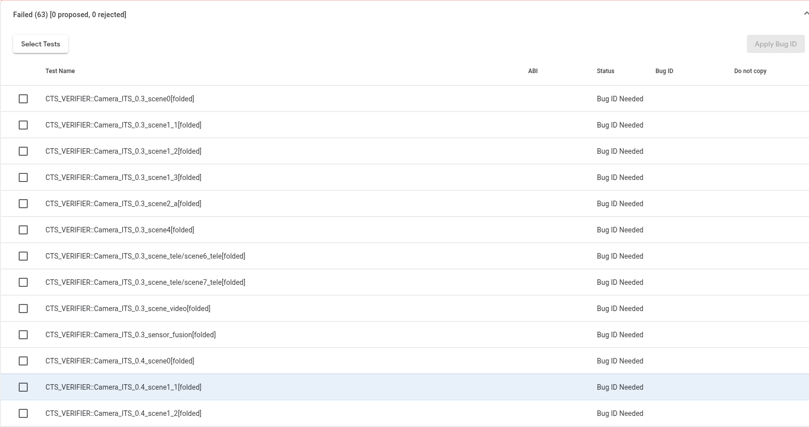
Figure 1. Documentation of scenes that were not executed or failed.
Passing scenes are listed under the Aggregated Pass section.
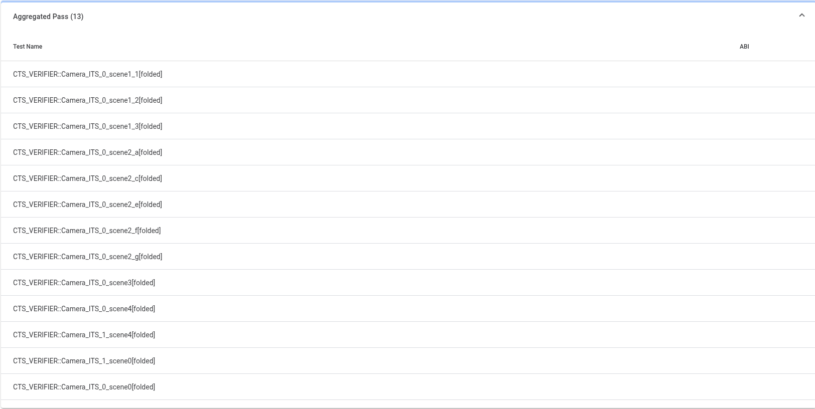
Figure 2. Scenes categorized as Aggregated Pass
Build approval status
Build approval is granted once all required scenes have completed successfully across the aggregated reports.
DNG noise model
Devices that advertise the ability to capture RAW or DNG must provide a noise model in the capture result metadata of each raw shot. This noise model must be embedded into the camera HAL for each camera (for example, front and back cameras) on the device that claims support.
Noise model implementation
To implement a noise model, follow these steps to generate a noise model and embed the model into the camera HAL.
To generate a noise model for each camera, run the
dng_noise_model.pyscript in thetoolsdirectory. This outputs a C code snippet. For more information on how to set up the camera and capture environment, see theDngNoiseModel.pdfdocument in thetoolsdirectory.To implement the noise model for the device, cut and paste the C code snippet into the camera HAL.
Noise model validation
The tests/scene1_1/test_dng_noise_model.py
automated ITS test validates the noise model by verifying that the noise values
for the shot exposure and gain provided in the camera data is correct.
Marginally passing tests (PASS* test status)
In Android 17 and higher, a marginal pass (PASS*)
indicates that a test has passed, but its performance metrics are very close to
the predefined passing threshold. While the test technically meets the passing
criteria, the proximity to the failure boundary suggests a need for closer
examination.
Benefits of marginal pass
The PASS* status offers several benefits:
Early warning system: Identifies tests that are on the verge of failing, allowing teams to address issues before they lead to outright failures.
Proactive optimization: Encourages teams to optimize tests and code that are performing at the lower end of the acceptable range, improving overall stability.
Improved quality: Helps maintain a higher standard of quality by flagging areas that might be susceptible to future regressions with minor code changes.
Reduced debugging time: By catching
PASS*tests early, the time and effort required to debug full failures in the future can be significantly reduced.
PASS* details
The PASS* status includes the following:
Defining thresholds: Specific marginal pass thresholds are defined for each relevant test in Camera ITS.
Automated detection: The test automation system detects and categorizes tests as
PASS*based on the defined thresholds.Alerting mechanism: Teams receive automated alerts for any tests flagged as
PASS*, directing them to investigate the specific test and its metrics.Reporting: Marginal pass statuses are clearly indicated in test reports and dashboards for better visibility as
PASS*in theItsTestSummaryreport, similar toFail*fornot_yet_mandatedtests. The test maintains a green status, as it continues to pass within the established thresholds, to avoid further confusion. ThePASS*status applies only to a test class, not the entire scene. For example, Scene_0 can be consideredPASSeven if test_jitter and test_metadata arePASS*.Monitoring: Performance data is collected on tests that marginally pass on a device. This allows for monitoring future camera improvements made by OEMs if these tests transition to a
PASSstatus.
The following is an example of test results with PASS*:
INFO:root:Reporting camera 1 ITS results to CtsVerifier
INFO:root:ITS results to CtsVerifier: {'scene0': {'result': 'PASS', 'TEST_STATUS': [{'test': 'test_jitter', 'status': 'PASS*'}, {'test': 'test_metadata', **'status': 'PASS*'**}, {'test': 'test_request_capture_match', 'status': 'PASS'}, {'test': 'test_sensor_events', 'status': 'PASS'}, {'test': 'test_solid_color_test_pattern', 'status': 'PASS'}, {'test': 'test_test_patterns', 'status': 'SKIP'}, {'test': 'test_tonemap_curve', 'status': 'SKIP'}, {'test': 'test_unified_timestamps', 'status': 'PASS'}, {'test': 'test_vibration_restriction', 'status': 'PASS'}], 'mpc_metrics': [], 'performance_metrics': [], 'feature_query_proto': [], 'feature_query_proto_path': [], 'summary': '/tmp/CameraITS_zojk4sdr/cam_id_1/scene0/scene_test_summary.txt', 'start': 1754330630345, 'end': 1754330764534}, 'scene1_1': {'result': 'NOT_EXECUTED'}, 'scene1_2': {'result': 'NOT_EXECUTED'}, 'scene1_3': {'result': 'NOT_EXECUTED'}, 'scene2_a': {'result': 'NOT_EXECUTED'}, 'scene2_b': {'result': 'NOT_EXECUTED'}, 'scene2_c': {'result': 'NOT_EXECUTED'}, 'scene2_d': {'result': 'NOT_EXECUTED'}, 'scene2_e': {'result': 'NOT_EXECUTED'}, 'scene2_f': {'result': 'NOT_EXECUTED'}, 'scene2_g': {'result': 'NOT_EXECUTED'}, 'scene3': {'result': 'NOT_EXECUTED'}, 'scene4': {'result': 'NOT_EXECUTED'}, 'scene6': {'result': 'NOT_EXECUTED'}, 'scene7': {'result': 'NOT_EXECUTED'}, 'scene8': {'result': 'NOT_EXECUTED'}, 'scene9': {'result': 'NOT_EXECUTED'}, 'scene_extensions/scene_hdr': {'result': 'NOT_EXECUTED'}, 'scene_extensions/scene_low_light': {'result': 'NOT_EXECUTED'}, 'scene_tele/scene6_tele': {'result': 'NOT_EXECUTED'}, 'scene_tele/scene7_tele': {'result': 'NOT_EXECUTED'}, 'scene_video': {'result': 'NOT_EXECUTED'}, 'scene5': {'result': 'NOT_EXECUTED'}, 'sensor_fusion': {'result': 'NOT_EXECUTED'}, 'feature_combination': {'result': 'NOT_EXECUTED'}, 'scene_flash': {'result': 'NOT_EXECUTED'}, 'scene_ip': {'result': 'NOT_EXECUTED'}}
Partners are encouraged to:
- Monitor
PASS*alerts - Investigate the root cause of
PASS*tests - Proactively optimize tests and code identified as
PASS*
The PASS* status aims to enhance the robustness and reliability of Camera ITS
testing, leading to a stable and high-quality product.