System audio Androida może odtwarzać i nagrywać sygnały audio na wiele sposobów, za pomocą różnych urządzeń peryferyjnych i konfiguracji. Ręczne testowanie podstawowych funkcji audio w złożonym systemie jest powolne i żmudne. Aby rozwiązać ten problem, CTS Verifier zawiera kilka testów ścieżek danych, które automatycznie weryfikują podstawowe możliwości audio na wielu trasach i w różnych konfiguracjach.
Testy ścieżek danych audio obejmują 3 obszary:
- Ścieżka gniazda słuchawek analogowych (jeśli jest dostępna)
- Ścieżka głośnika i mikrofonu na urządzeniu
- Ścieżka peryferyjnego urządzenia audio USB (zestaw słuchawkowy USB i interfejs audio USB)
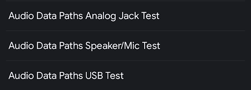
Rysunek 1. Panel list testowych ścieżek danych audio.
Typowe elementy
Przed uruchomieniem testu w panelu testów wyświetlają się te informacje:
Lista atrybutów audio i informacja o tym, czy są obsługiwane przez testowane urządzenie. Ta lista określa, które ścieżki danych i specyfikacje atrybutów można uruchomić. Na przykład ścieżka danych lub atrybuty ścieżek MMAP nie są uruchamiane na urządzeniach, które nie obsługują MMAP.
- Mikrofon – urządzenie zawiera wbudowany mikrofon.
- Głośnik – urządzenie zawiera wbudowany głośnik.
- MMAP – urządzenie obsługuje tryb audio MMAP.
- MMAP Exclusive – urządzenie obsługuje tryb audio MMAP Exclusive.
Wybór interfejsów API audio
- Java API – odtwarzanie i nagrywanie odbywa się za pomocą interfejsu Java Audio API.
- Natywny interfejs API – odtwarzanie i nagrywanie odbywa się za pomocą natywnego interfejsu API audio.
Przycisk Skalibruj dźwięk, który otwiera panel kalibracji pętli audio, aby ustawić poziom sygnału przed uruchomieniem testów.
Przyciski procesu testowania:
Rozpocznij – rozpoczyna sekwencję testową. Testowane są wszystkie ścieżki danych lub konfiguracje, które można przetestować i które zakończyły się niepowodzeniem.
Anuluj – zatrzymuje bieżącą sekwencję testową.
Wyczyść wyniki – czyści kod wyniku dla wszystkich ścieżek danych. Tej opcji można użyć, aby uruchomić pełną sekwencję testów po poprzednich testach, które mogły się nie powieść.
Panel wyświetlania sygnału (oscyloskop). Ten panel pokazuje sygnał podczas przeprowadzania testów. Wyświetlany sygnał, który nie pokazuje czystej sinusoidy o wysokiej amplitudzie, wskazuje na problematyczną ścieżkę danych.
Liczba wyświetlanych próbek zmienia się w zależności od ścieżki danych lub konfiguracji, więc normalne jest, że pojawia się różna liczba cykli fali sinusoidalnej.
Lista ścieżek danych lub specyfikacji konfiguracji poddanych testowi. Wyświetla listę możliwych konfiguracji do uruchomienia na urządzeniu peryferyjnym wejścia/wyjścia audio powiązanym z wybranym testem ścieżek danych. Ścieżki danych lub konfiguracje, które są prawidłowe w przypadku testowanego urządzenia i dostępnych urządzeń peryferyjnych podłączonych do testowanego urządzenia, są oznaczone gwiazdką. Obok nich znajduje się stan testu (ZALICZONO, NIE ZALICZONO lub NIE PRZETESTOWANO).
Podczas testu bieżąca ścieżka danych lub konfiguracja jest oznaczona symbolem >> << otaczającym specyfikację.
Więcej informacji znajdziesz na rysunku poniżej:
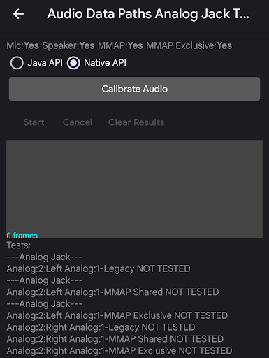
Rysunek 2. Panel testowy ścieżek danych audio.
Test ścieżek danych audio – gniazdo analogowe
Test ścieżek danych audio gniazda analogowego sprawdza podstawowe możliwości audio za pomocą ścieżki słuchawek analogowych. Jeśli urządzenie nie ma analogowego gniazda słuchawkowego, automatycznie przyznawany jest wynik ZALICZONO.
Wymagane urządzenia peryferyjne
Więcej informacji znajdziesz w artykule Wtyczka pętli zwrotnej audio.
Na ilustracjach poniżej przedstawiono ekrany testu gniazda audio ścieżek danych audio przed jego ukończeniem i po nim:
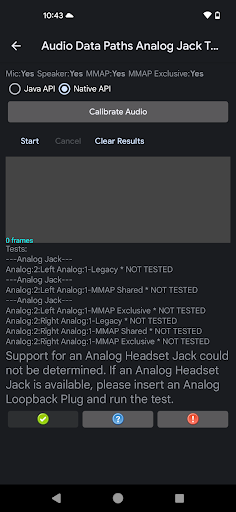
Rysunek 3. Test gniazda analogowego ścieżki danych audio jest gotowy do uruchomienia.
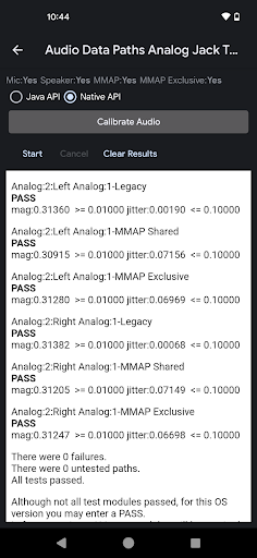
Rysunek 4. Ścieżka danych audio – test gniazda analogowego po pomyślnym zakończeniu.
Aby uruchomić test ścieżek danych audio na gnieździe analogowym:
- Włóż wtyczkę pętli zwrotnej do gniazda słuchawek analogowych na testowanym urządzeniu. Lista testów zostanie zaktualizowana i będą na niej widoczne prawidłowe ścieżki danych.
- Użyj panelu kalibracji pętli audio, aby ustawić odpowiedni poziom sygnału.
Kliknij Rozpocznij. Test sprawdza każdą ścieżkę danych lub konfigurację i mierzy wielkość sygnału oraz jitter, aby określić, czy ścieżka danych lub konfiguracja działa prawidłowo.
Możesz obserwować wyświetlanie sygnału, aby wizualnie sprawdzić, czy wygląda on prawidłowo. Po uruchomieniu testu wyświetlany jest wynik dla każdej ścieżki danych lub konfiguracji.
Po zakończeniu sekwencji testowej wyświetlacz sygnału i ścieżki danych lub lista konfiguracji zostaną zastąpione panelem z wynikami. Błędy w przypadku części nieudanego testu (np. wielkości lub drgań) są wyświetlane w kolorze czerwonym wraz z nieosiągniętym progiem lub wymaganiem.
Kliknij ZDAJĘ lub NIE ZDAJĘ.
Test ścieżek danych audio głośnika i mikrofonu
Test ścieżek danych audio głośnika i mikrofonu sprawdza podstawowe możliwości audio za pomocą ścieżki głośnika i mikrofonu na urządzeniu.
Wymagane urządzenia peryferyjne
Do przeprowadzenia tego testu nie są potrzebne żadne urządzenia zewnętrzne.
Na ilustracjach poniżej przedstawiono ekrany ścieżek danych audio głośnika i mikrofonu przed testem i po jego zakończeniu. Błędy są zaznaczone na czerwono:
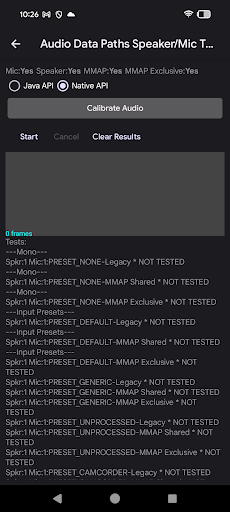
Rysunek 5. Ścieżka danych audio – test głośnika i mikrofonu gotowy do uruchomienia.
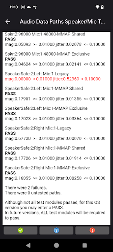
Rysunek 6. Ścieżka danych audio – test głośnika i mikrofonu po pomyślnym zakończeniu.
Aby przeprowadzić test głośnika i mikrofonu na ścieżkach danych audio:
- Umieść DUT płasko na biurku lub stole w cichym otoczeniu. Głośne dźwięki podczas testu mogą zakłócać analizę zarejestrowanego dźwięku.
- Użyj panelu kalibracji pętli audio, aby ustawić odpowiedni poziom sygnału.
Kliknij Rozpocznij. Test obejmuje każdą ścieżkę danych lub konfigurację, mierząc wielkość sygnału i jitter, aby określić, czy ścieżka danych lub konfiguracja działa prawidłowo.
Możesz monitorować wyświetlanie sygnału, aby wizualnie sprawdzić, czy wygląda on prawidłowo. W trakcie testu wyświetlane są wyniki dla każdej ścieżki danych lub konfiguracji.
Po zakończeniu sekwencji testowej wyświetlacz sygnału i ścieżki danych lub lista konfiguracji zostaną zastąpione panelem z wynikami. Błędy w przypadku części nieudanego testu (np. wielkości lub drgań) są wyświetlane w kolorze czerwonym wraz z nieosiągniętym progiem lub wymaganiem.
Kliknij ZDAJĘ lub NIE ZDAJĘ.
Test ścieżek danych audio USB
Test ścieżek danych audio USB sprawdza podstawowe możliwości audio na ścieżce USB audio (słuchawki USB i interfejs audio USB).
Wymagane urządzenia peryferyjne
Więcej informacji znajdziesz w artykule Interfejs audio USB.
Na ilustracjach poniżej przedstawiono ekrany ścieżek danych audio USB test przed ukończeniem i po ukończeniu:
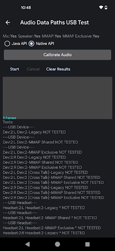
Rysunek 7. Test USB ścieżki danych audio jest gotowy do uruchomienia.
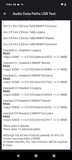
Rysunek 8. Test ścieżki danych audio USB po pomyślnym zakończeniu.
Aby uruchomić test ścieżek danych audio USB:
Podłącz urządzenie peryferyjne audio USB do DUT. Sekwencję testową należy uruchomić osobno w każdym z tych przypadków:
- Adapter słuchawek USB na analogowe z włożoną wtyczką pętli zwrotnej
- Interfejs audio USB z kablowymi połączeniami wyjść z wejściami
Użyj panelu kalibracji pętli audio, aby ustawić odpowiedni poziom sygnału.
Kliknij Rozpocznij. Test obejmuje każdą ścieżkę danych lub konfigurację, mierząc wielkość sygnału i jitter, aby określić, czy ścieżka danych lub konfiguracja działa prawidłowo.
Możesz monitorować wyświetlanie sygnału, aby wizualnie sprawdzić, czy wygląda on prawidłowo. W trakcie testu wyświetlane są wyniki dla każdej ścieżki danych lub konfiguracji.
Po zakończeniu sekwencji testowej wyświetlacz sygnału i ścieżki danych lub lista konfiguracji zostaną zastąpione panelem z wynikami. Błędy w przypadku części nieudanego testu (np. wielkości lub drgań) są wyświetlane w kolorze czerwonym wraz z nieosiągniętym progiem lub wymaganiem.
Powtórz kroki 1–3 w przypadku nieprzetestowanego urządzenia peryferyjnego USB.
Kliknij ZDAJĘ lub NIE ZDAJĘ.
Interpretacja wyników testu
Dla każdej konfiguracji na wyjściu generowana jest fala sinusoidalna, a na wejściu rejestrowany jest sygnał. Test próbuje wykryć na wejściu falę sinusoidalną o częstotliwości takiej samej jak wygenerowany dźwięk.
W przypadku każdej konfiguracji wyświetlane są pomiary wielkości i drgań, które są zdefiniowane w ten sposób:
Amplituda: amplituda (lub poziom) wejściowej fali sinusoidalnej jest analizowana w sposób podobny do szybkiej transformaty Fouriera (FFT). Jeśli wartość jest zbyt niska, może to oznaczać, że sygnał jest zablokowany lub że określony kanał nie działa. Może to też oznaczać, że głośność wyjściowa lub wzmocnienie wejściowe są zbyt niskie. Aby przejść test, wielkość musi osiągnąć określony poziom.
Jitter: faza zarejestrowanej sinusoidy jest również mierzona względem wygenerowanego sygnału. Stała faza względna wskazuje, że zarejestrowany sygnał odpowiada wygenerowanemu sygnałowi. Jeśli faza względna się zmienia, wygenerowany sygnał jest uszkodzony lub rejestrowany jest inny sygnał, np. szum. Zmiany fazy względnej nazywane są jitterem.
Jeśli dane wejściowe rejestrują tylko głośny dźwięk, jego wielkość może być duża, ponieważ hałas może zawierać wszystkie częstotliwości fali sinusoidalnej. W takim przypadku analizator nie może zablokować wygenerowanej fali sinusoidalnej, co powoduje duże drgania.
W tabeli poniżej zinterpretowano wyniki dla różnych kombinacji pomiarów wielkości i drgań:
| Wielkość | Zakłócenia | Wynik | Interpretacja |
|---|---|---|---|
| Wysoki | Niska | POZYTYWNY WYNIK | Rejestrowana jest czysta wersja wyjściowej fali sinusoidalnej. |
| Wysoki | Wysoki | NEGATYWNY WYNIK | Zostanie zarejestrowany głośny dźwięk lub bardzo zniekształcony sygnał. |
| Niska | Niska | NEGATYWNY WYNIK | Czysty sygnał jest nagrywany na zbyt niskim poziomie. |
| Niska | Wysoki | NEGATYWNY WYNIK | Zarejestrowano cichy sygnał, który jest uszkodzony lub zaszumiony. |
Jeśli test CTS Verifier się nie powiedzie, uruchom test Data Paths w najnowszej wersji OboeTester. Narzędzie OboeTester drukuje szczegółowy raport i może pomóc w rozwiązaniu problemu.
