
多くの CTS 検証ツールによるテストでは、生成された信号を測定するため(オーディオ信号を出力から入力にループバックするため)、オーディオ ループバック システムが必要です。そのためには、確実にキャプチャできる十分な大きさの信号を生成する必要があります。その調整を簡単に行えるように、オーディオ ループバックのキャリブレーション パネルには、あらゆるループバック CTS テストからアクセスし、テスト開始前に適切な信号の振幅を設定できるようになっています。
オーディオ ループバックのキャリブレーション パネルの使用
オーディオ ループバックのキャリブレーション パネルは、次の図のように、オーディオ ループバックを使用する CTS 検証ツールによるテストで、[Calibrate Audio] を押すことで表示できます。
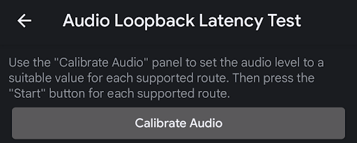
図 1. オーディオ ループバック レイテンシ テスト
以下の図がキャリブレーション パネルです。
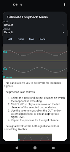
図 2. オーディオ ループバックのキャリブレーション パネル
調整するループバック周辺機器を選択
調整するループバック周辺機器を選択する方法として最も簡単なのは、調整するオーディオ周辺機器を接続することです。または、内蔵スピーカーとマイク間のループバックの場合は、どのデバイスも接続せず、[Input] と [Output] を [Default] に設定したままにします。
左のチャンネルを調整
[Left] ボタンを押し、周辺機器の左のチャンネルで信号を再生します。DUT の音量ボタンを使用して音量を調整します。周辺機器が、入力レベルのコントロール機能がある外部 USB インターフェースの場合は、ディスプレイに表示される信号が適切になるまで、そのコントロールを適宜調整します。
信号が小さすぎる
次の図は左のチャンネル上の信号ですが、振幅の大きさがテストには不十分です。信号のレベルを高めます。
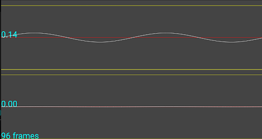
図 3. 信号が小さすぎる
信号が大きすぎる
次の図を見ると、左のチャンネルの信号の振幅が大きすぎるため、キャプチャ デバイスでクリッピングされており、テストには適さない信号であることがわかります。信号のレベルを下げます。
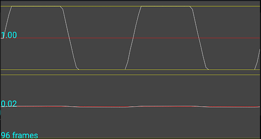
図 4. 信号が大きすぎる
最適な信号
次の図の例では、左のチャンネルの信号がテストに最適になっています。
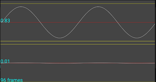
図 5. 最適な信号
右のチャンネルを調整
[Right] ボタンを押し、周辺機器の右のチャンネルで信号を再生します。左のチャンネルの調整にまとめられているプロセスに沿って、テストに最適なレベルを設定します。
単一チャンネルのキャプチャ デバイスを調整
チャンネルが 1 つしかないキャプチャ周辺機器(内蔵マイクや、アナログ ヘッドセット イヤホン差込口に接続されたループバック プラグなど)の場合、ディスプレイでは、どちらのチャンネルを再生するかに関係なく、両方のチャンネルで同じ信号が表示されます。この動作に問題はなく、信号レベルは左のチャンネルの調整の説明に沿って設定する必要があります。
入力および出力周辺機器の明示的な選択
調整するループバック周辺機器の選択に記載されているように、特定のループバック周辺機器を調整する際は、そのデバイスを接続し(スピーカーとマイクのルートの場合は接続せず)、[Input] と [Output] メニューで [Default] を選択する方法が最も簡単です。ただし、デバッグの際には、メニューから利用可能なデバイスを選択すると便利な場合があります。これらのリストには、現在利用できる周辺機器の入力ルートと出力ルートがすべて表示されます。