
หน้านี้ให้ข้อมูลเกี่ยวกับวิธีซื้อหรือประกอบ Sensor Fusion
Box Sensor Fusion Box ใช้ในการทดสอบ sensor_fusion ของ CameraITS และการทดสอบmulti-cameraการซิงค์ โดยจะให้สภาพแวดล้อมการทดสอบที่สอดคล้องกันสำหรับ
การวัดความแม่นยำของไทม์สแตมป์ของเซ็นเซอร์สำหรับอุปกรณ์ Android
โดยเฉพาะเซ็นเซอร์รูปภาพของกล้องและไจโรสโคป โดยประกอบด้วย
ชิ้นส่วนกล่องพลาสติกที่ตัดด้วยเลเซอร์จาก
ภาพวาดการออกแบบโดยใช้คอมพิวเตอร์ช่วย (CAD) และกล่องควบคุมเซอร์โว
คุณจะซื้อ Sensor Fusion Box หรือสร้างเองก็ได้
ซื้อ Sensor Fusion Box
เราขอแนะนำให้ซื้อ Sensor Fusion Box จากผู้ให้บริการที่มีคุณสมบัติตามเกณฑ์ต่อไปนี้
Byte Bridge Inc.
USA: 1502 Crocker Ave, Hayward, CA 94544-7037
China: 22F #06-08, Hongwell International Plaza Tower A, 1600 West Zhongshan Road, Xuhui, Shanghai, 200235
www.bytebt.com
androidpartner@bytebt.com
USA: +1-510-373-8899
China: +86-400-8866-490JFT CO LTD 捷富通科技有限公司 (เดิมชื่อ MYWAY DESIGN)
จีน: No. 40, Lane 22, Heai Road, Wujing Town, Minhang District, Shanghai, China
ไต้หวัน: 4F., No. 163, Fu-Ying Road, XinZhuang District, New Taipei City 242, Taiwan
www.jftcoltd.com
service@jfttec.com หรือ its.sales@jfttec.com
จีน:+86-021-64909136
ไต้หวัน: 886-2-29089060
สร้างกล่องฟิวชันเซ็นเซอร์
ส่วนนี้มีวิธีการทีละขั้นตอนสำหรับการประกอบ Sensor Fusion Box จากชิ้นส่วนอะคริโลไนไตรล์บิวทาไดอีนสไตรีน (ABS) ที่ตัดด้วยเลเซอร์ (แสดงใน รูปที่ 1)
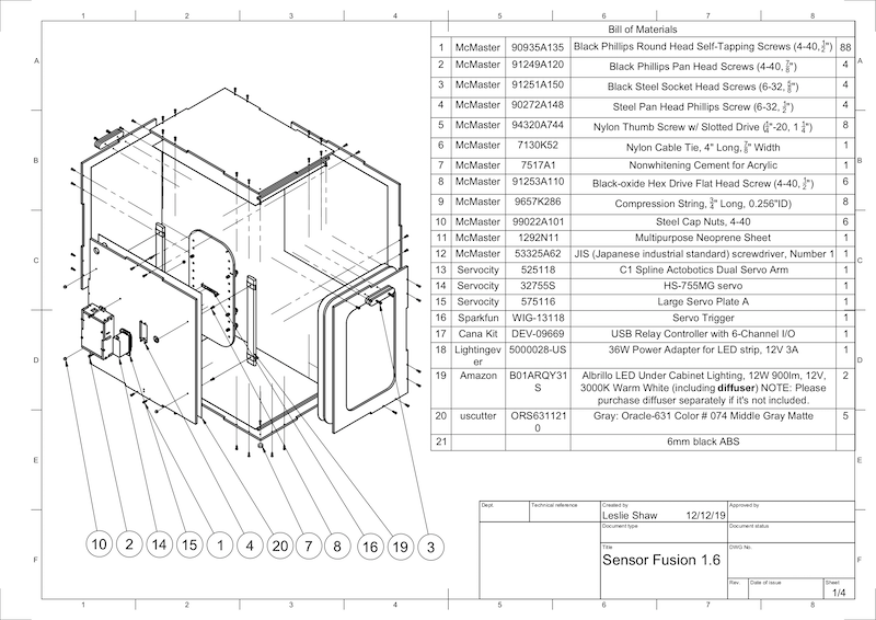
รูปที่ 1 ภาพวาดทางกลของส่วนประกอบ Sensor Fusion Box
เครื่องมือที่จําเป็น
ก่อนเริ่มต้น โปรดตรวจสอบว่าคุณได้ดาวน์โหลดแบบทางเทคนิคสำหรับ Sensor Fusion Box (รวมอยู่ใน ไฟล์ ZIP ของ Sensor Fusion Box) และมีเครื่องมือต่อไปนี้
- ไขควงปากแฉก
- ไขควงหัว JIS
- ประแจหกเหลี่ยม
- ชุดสว่านไฟฟ้า
- มีด X-ACTO
- เทป
ขั้นตอนที่ 1: ติดสติกเกอร์ไวนิล
หลังจากสร้างคอมโพเนนต์ ABS ด้วยเครื่องตัดเลเซอร์แล้ว ให้ติดสติกเกอร์ไวนิลบนกล่องพลาสติกเพื่อให้ควบคุมสีได้อย่างเหมาะสมที่ด้านในของกล่องทดสอบ โดยทำดังนี้
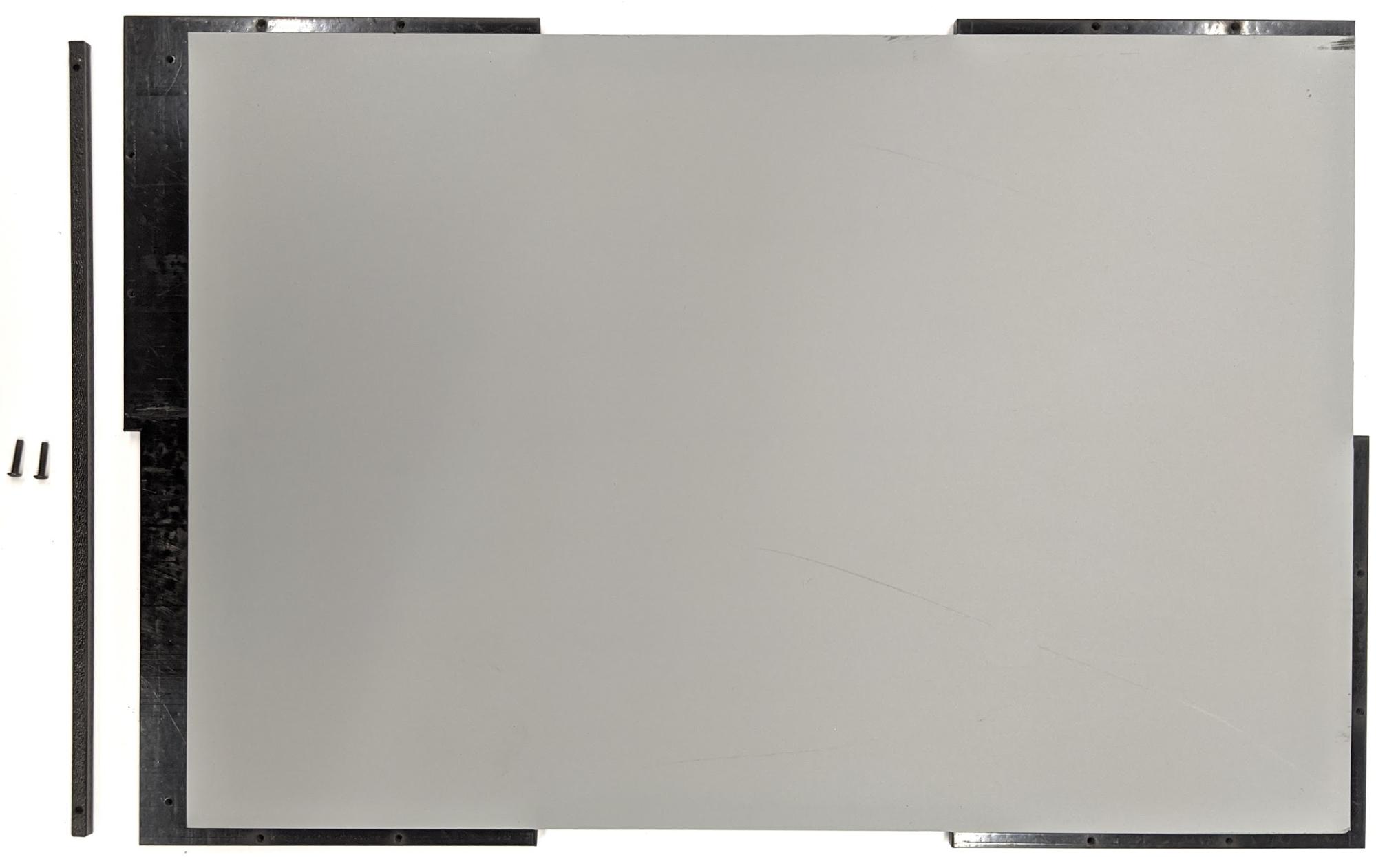
ติดไวนิลที่ด้านเรียบของ ABS ดังแสดงในรูปที่ 2 ดูเคล็ดลับที่เป็นประโยชน์เกี่ยวกับการติดไวนิลได้ที่ wikiHow
ตัดรูที่จำเป็นบนไวนิลด้วยมีดอเนกประสงค์
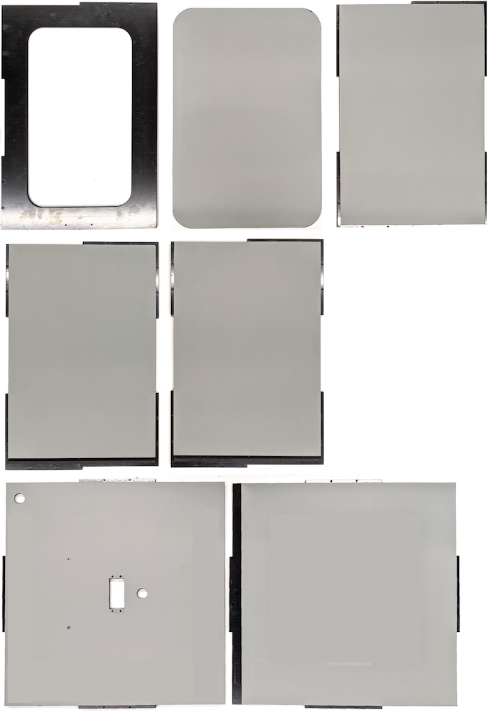
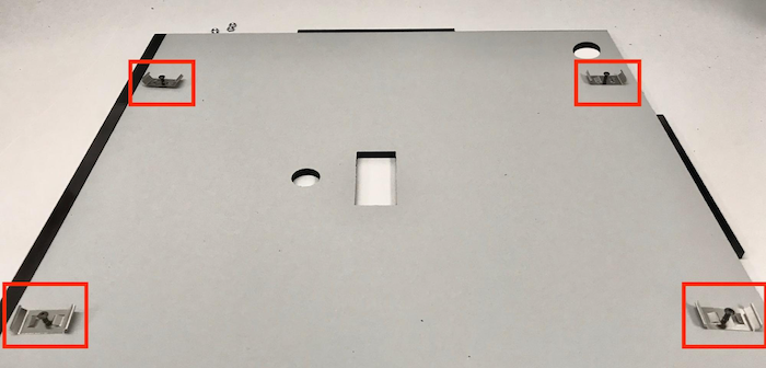
รูปที่ 2 ชิ้นส่วน ABS ที่ติดไวนิลด้านเรียบ (ด้านในของกล่อง)ใช้กาวอะคริลิกติดชิ้นส่วน ABS ทรงกลมที่มุมทั้ง 4 ของ แผงด้านล่าง
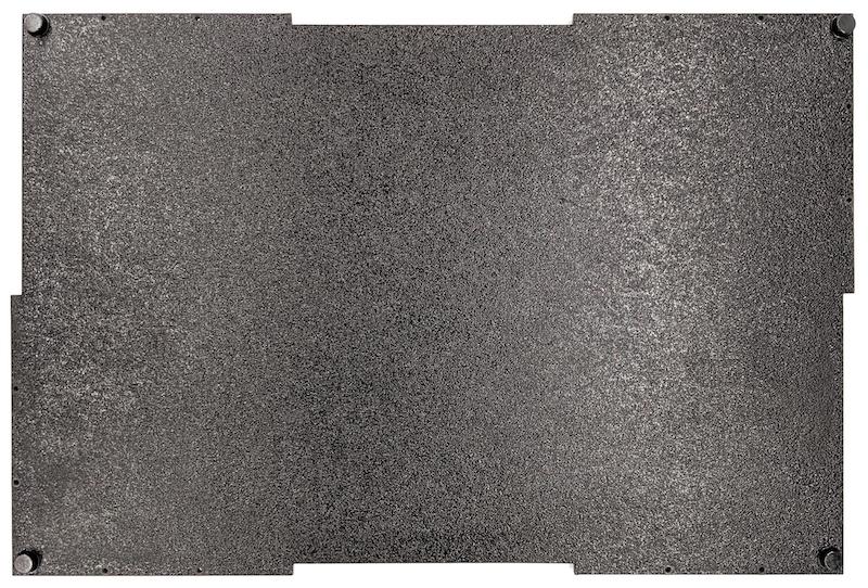
รูปที่ 3 แผงด้านล่างที่มีชิ้นส่วน ABS ทรงกลมติดกาวไว้ที่มุมทั้ง 4
ขั้นตอนที่ 2: เตรียมที่ยึดโทรศัพท์และติดที่ยึดเซอร์โว
วิธีเตรียมที่ยึดโทรศัพท์เพื่อติดกับเซอร์โว
แตะ 20 รูบนอุปกรณ์ยึดโทรศัพท์ด้วยดอกสว่านขนาด 1/4"-20
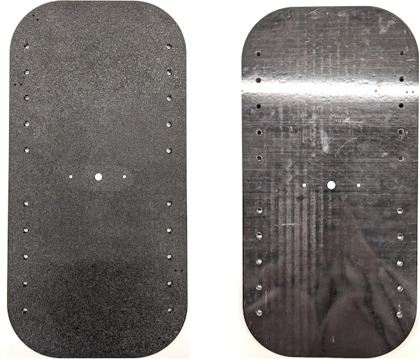
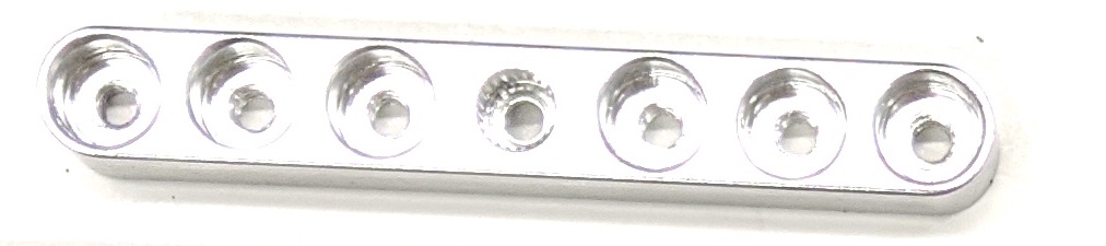
รูปที่ 4 อุปกรณ์ยึดโทรศัพท์ที่มีรูเจาะตรวจสอบว่าคุณมีช่อง ABS, สกรูหัวแม่มือไนลอน, น็อตไนลอน (สำหรับปรับความสูงของสกรูหากจำเป็น), สปริง C1 แขนเซอร์โวคู่ของ Actobotics, สกรู 4-40 และสปริงอัด
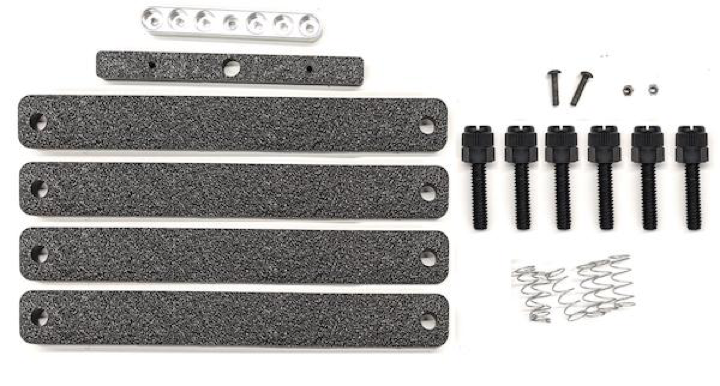
รูปที่ 5 ชิ้นส่วนของที่ยึดโทรศัพท์ขันสกรู 4-40 และขัน (1.2 N*m หรือ 8.9 in*lbf) แขนเซอร์โวเข้ากับด้านหลังของที่ยึดโทรศัพท์ ใช้สกรูและน็อตหัวกลม 4-40 ตัวเดิม ขันช่อง ABS สำหรับตัวคั่นโทรศัพท์ที่ด้านหน้าของ ที่ยึดโทรศัพท์
รูปที่ 6 ก้านที่ด้านหลังของฟิกซ์เจอร์ ขันให้แน่นด้วยสกรูที่ใส่จากด้านหน้า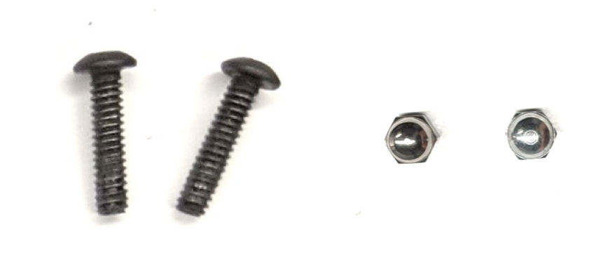
รูปที่ 7 สกรูยาว 3/4 นิ้วและน็อตหัวปิด 4-40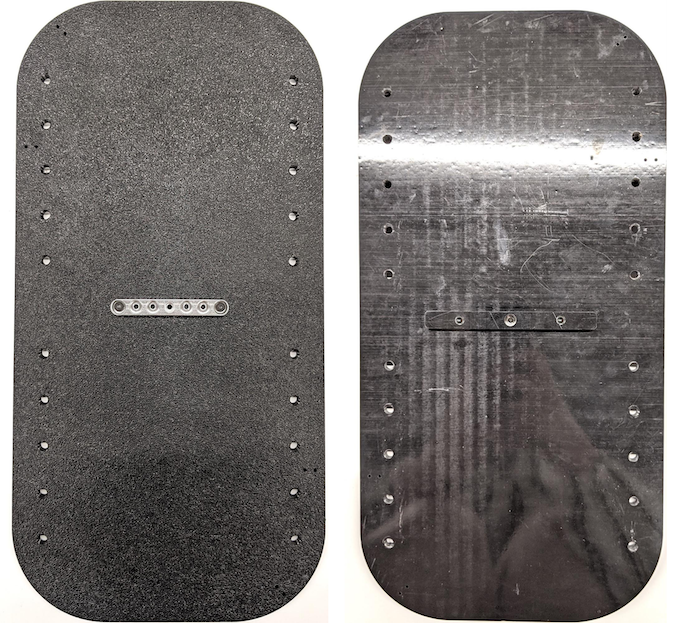
รูปที่ 8 ด้านหลัง (ซ้าย) และด้านหน้า (ขวา) ของที่ยึดโทรศัพท์
ขั้นตอนที่ 3: ติดแคลมป์โทรศัพท์
วิธีติดแคลมป์โทรศัพท์
ตัดแผ่นนีโอพรีนตามรูปร่างของตัวยึด ABS ที่ตัดออก แต่เว้นให้สั้นกว่า 1 นิ้วจากปลายทั้ง 2 ด้านตามที่แสดงในรูปที่ 9 หลังจากตัดแผ่นนีโอพรีนตามนั้นแล้ว ให้ติดชิ้นส่วนกับแคลมป์ ABS cut-out ตามรูปที่ 8
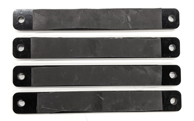
รูปที่ 9 แคลมป์ ABS ที่ติดแผ่นนีโอพรีนติดสกรูหัวแม่มือไนลอนและลวดสปริงเข้ากับแคลมป์ เพิ่มน็อตไนลอน เพื่อลดความยาวของสกรูตามต้องการ
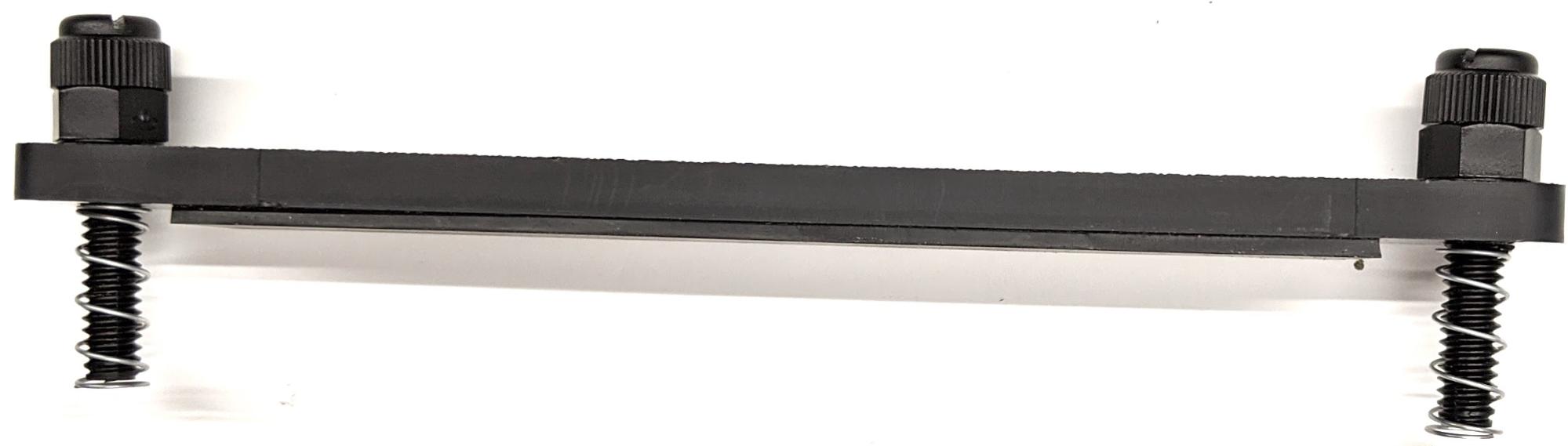
รูปที่ 10 แคลมป์พร้อมแผ่นนีโอพรีน สกรูหัวแม่มือ น็อตไนลอน และ ลวดสปริงขันสกรูหัวแม่มือของแคลมป์โทรศัพท์เข้ากับรูที่เจาะของฟิกซ์เจอร์โทรศัพท์ตามที่แสดงในรูปที่ 11 คุณปรับตำแหน่งของที่ยึดโทรศัพท์ได้ตามขนาดของโทรศัพท์
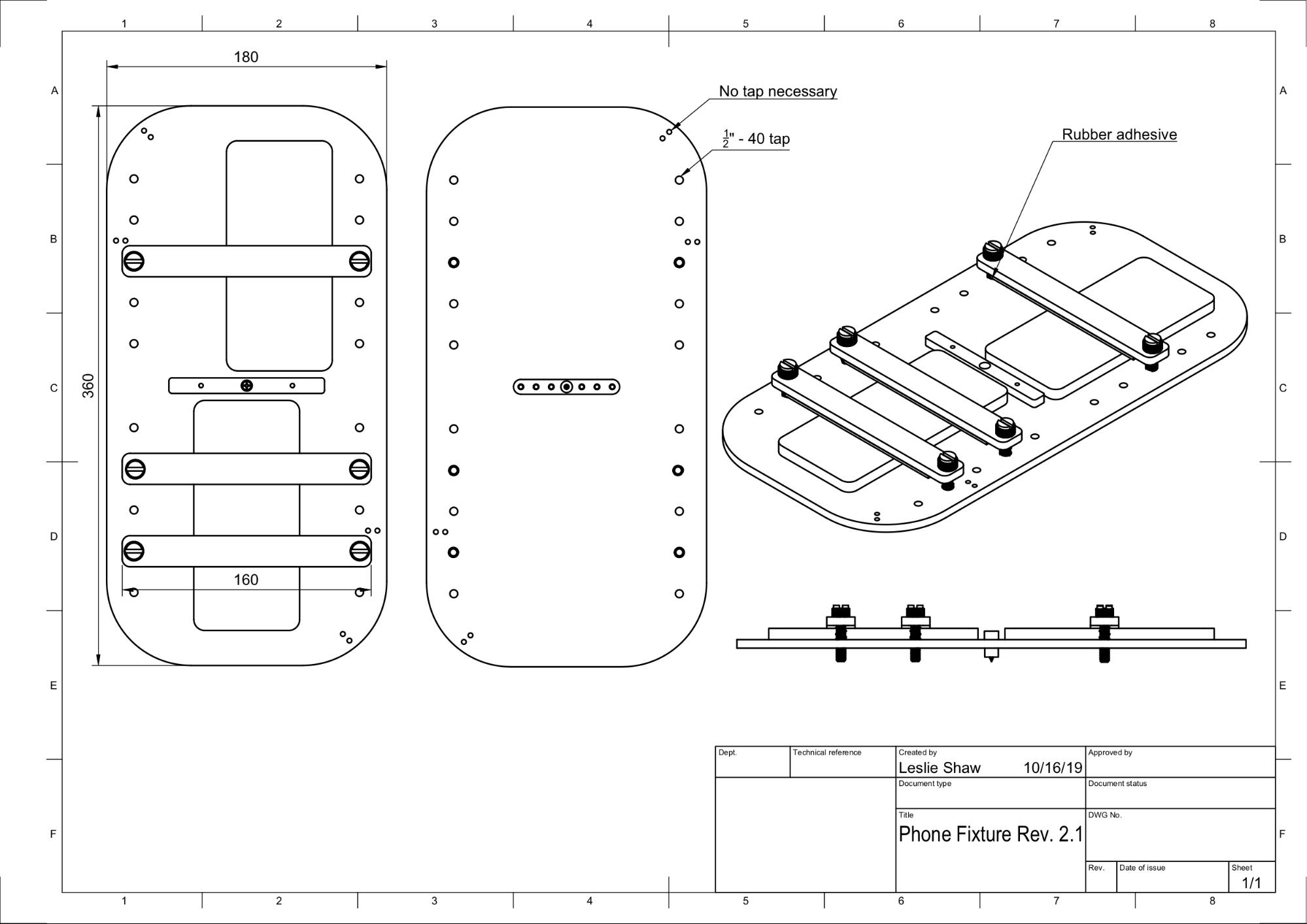
รูปที่ 11 ภาพวาดเชิงกลของอุปกรณ์ยึดโทรศัพท์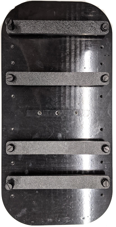
รูปที่ 12 อุปกรณ์ยึดโทรศัพท์ที่ประกอบแล้ว
ขั้นตอนที่ 4: ประกอบรางประตูบานเลื่อน
ยึดรางแผงเลื่อนที่ด้านบนและด้านล่างของกล่องไปทางด้านหน้า รูปที่ 13 แสดงสกรู 6-32 ในรูที่เจาะไว้ล่วงหน้า หรือจะใช้ สกรูเกลียวปล่อยก็ได้
รูปที่ 13 รางเลื่อนแบบคงที่ที่ด้านบนและด้านล่างของกล่อง
ขั้นตอนที่ 5: ติดตั้งไฟ
วิธีติดขายึดไฟและตัวกระจายแสง
วางชิ้นส่วนด้ามจับ 2 ชิ้นซ้อนกันแล้วประกอบเข้าด้วยกันโดยใช้สกรู 6-32 (หรือใช้สกรูเกลียวปล่อย)
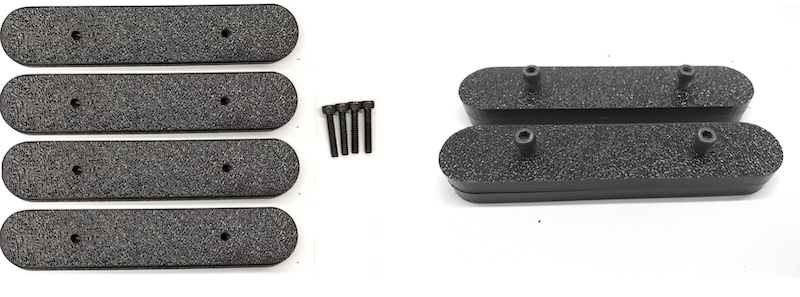
รูปที่ 14 ชิ้นส่วนและชุดประกอบของกล่อง Sensor Fusionเตรียมสกรู 4-40, น็อต และน็อตโดม 4 ตัวเพื่อยึดขายึด จากชุดไฟกับผนังของกล่อง
รูปที่ 15 สกรู 4-40 และขายึดไฟบนผนังด้านในของกล่อง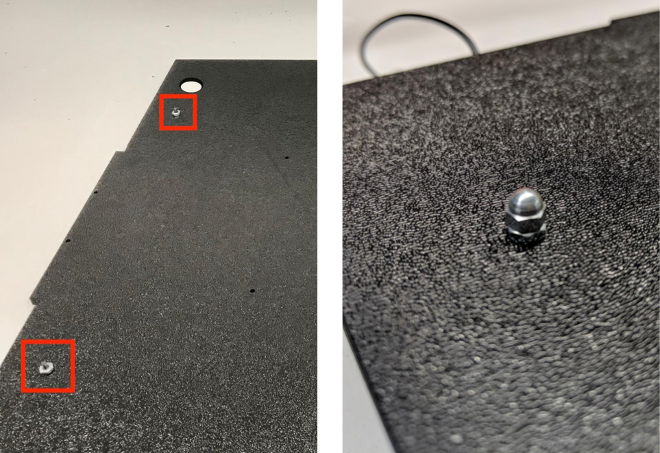
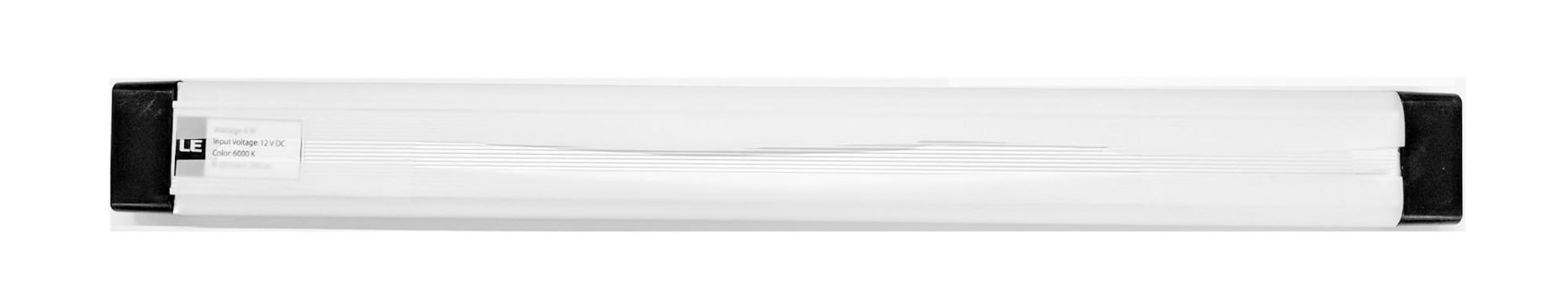
รูปที่ 16 สลักเกลียวและสลักเกลียวหัวกลมที่ขันเข้ากับสกรูจากภายนอก ของกล่องตัดตัวกระจายแสงให้มีขนาดที่เหมาะสมเพื่อพันแถบไฟ (ไม่จำเป็นหากไฟมีตัวกระจายแสงมาให้)
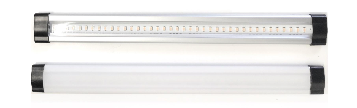
รูปที่ 17 แถบไฟและตัวกระจายแสงพันตัวกระจายแสงรอบแถบไฟและติดเทปที่ด้านหลัง
รูปที่ 18 ติดแถบไฟและตัวกระจายแสงจากด้านหลังติดไฟเข้ากับขายึด (อาจแน่นพอดี)
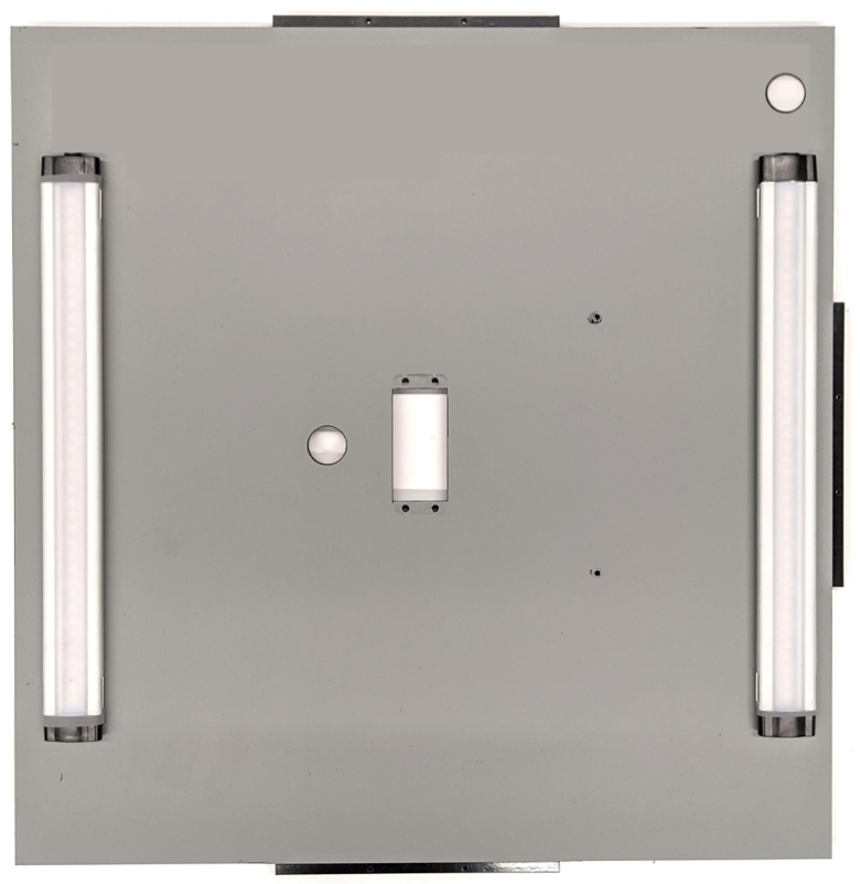
รูปที่ 19 ไฟที่ติดตั้งในวงเล็บ
ขั้นตอนที่ 6: ติดตั้งอุปกรณ์ยึดโทรศัพท์กับเพลตเซอร์โว
วิธีติดอุปกรณ์ยึดโทรศัพท์เข้ากับเพลตเซอร์โว
เตรียมสกรู 6-32 จำนวน 4 ตัวและเพลตเซอร์โวเพื่อยึดเซอร์โวกับผนัง ยึดเซอร์โวกับผนังด้านในและขันสกรูจากด้านใน เข้าไปในเพลตเซอร์โวบนผนังด้านนอก
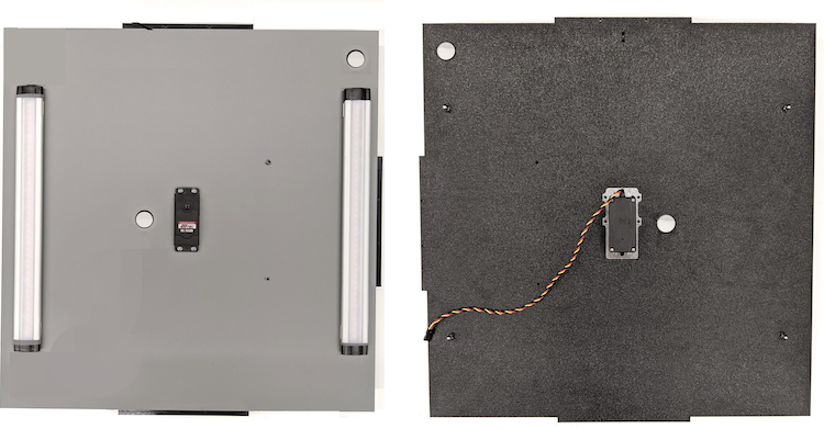
รูปที่ 20 ยึดเซอร์โวและเพลตเซอร์โวด้วยสกรู 6-32ยึดอุปกรณ์โทรศัพท์เข้ากับเซอร์โวด้วยน็อตล็อก (ดันตรงกลางของ เพลาเข้าไปที่ศูนย์กลางการหมุนของเซอร์โว)
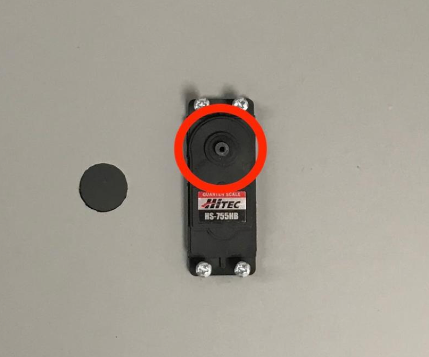
รูปที่ 21 เฟืองเซอร์โว
ใช้สกรูเซอร์โวที่มาพร้อมกับเซอร์โว ขันสกรู (1.2 N*m หรือ 8.9 in*lbf) อุปกรณ์ยึดโทรศัพท์เข้ากับเกียร์เซอร์โวผ่าน อาร์มเซอร์โว
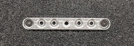
รูปที่ 22 แขนเซอร์โว
ขั้นตอนที่ 7: การประกอบขั้นสุดท้าย
วิธีประกอบกล่องฟิวชันเซ็นเซอร์ให้เสร็จสมบูรณ์
ตั้งแต่ Android 13 เป็นต้นไป อุปกรณ์ทดสอบการรวมเซ็นเซอร์จะมาพร้อมกับตัวควบคุมแสง Arduino ของ Android 13 (ใน Android 12 หรือต่ำกว่า อุปกรณ์รวมเซ็นเซอร์ที่จัดส่งมาพร้อมกับตัวควบคุม Arduino แบบ 6 แชแนลหรือตัวควบคุม Canakit อุปกรณ์ที่ใช้ Android 11 ถึง Android 12 จะใช้ได้กับตัวควบคุม Android 13, ตัวควบคุม Arduino แบบ 6 ช่อง หรือตัวควบคุม Canakit) ต่อส่วนขยายเซอร์โวเข้ากับช่องใดก็ได้ของ ตัวควบคุมเซอร์โว โดยที่ GND จะตรงกับสายสีดำ, VCC จะตรงกับ สายสีแดง และ SIG จะตรงกับสายสีเหลือง
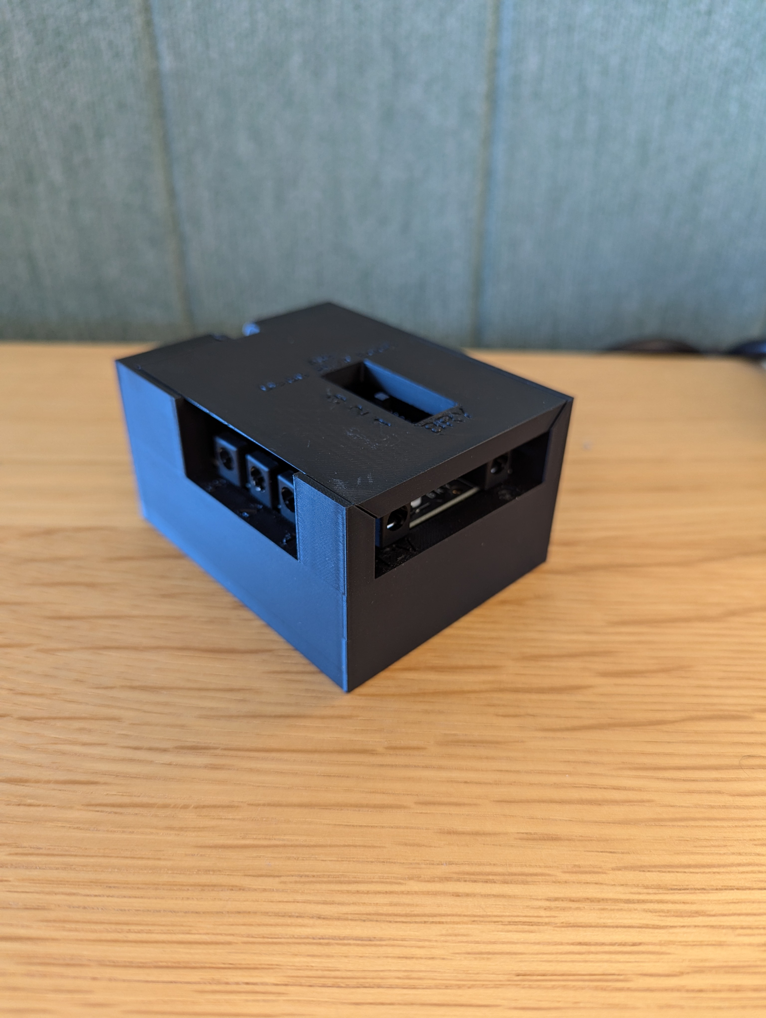
รูปที่ 23 Arduino Lighting Controller Rev3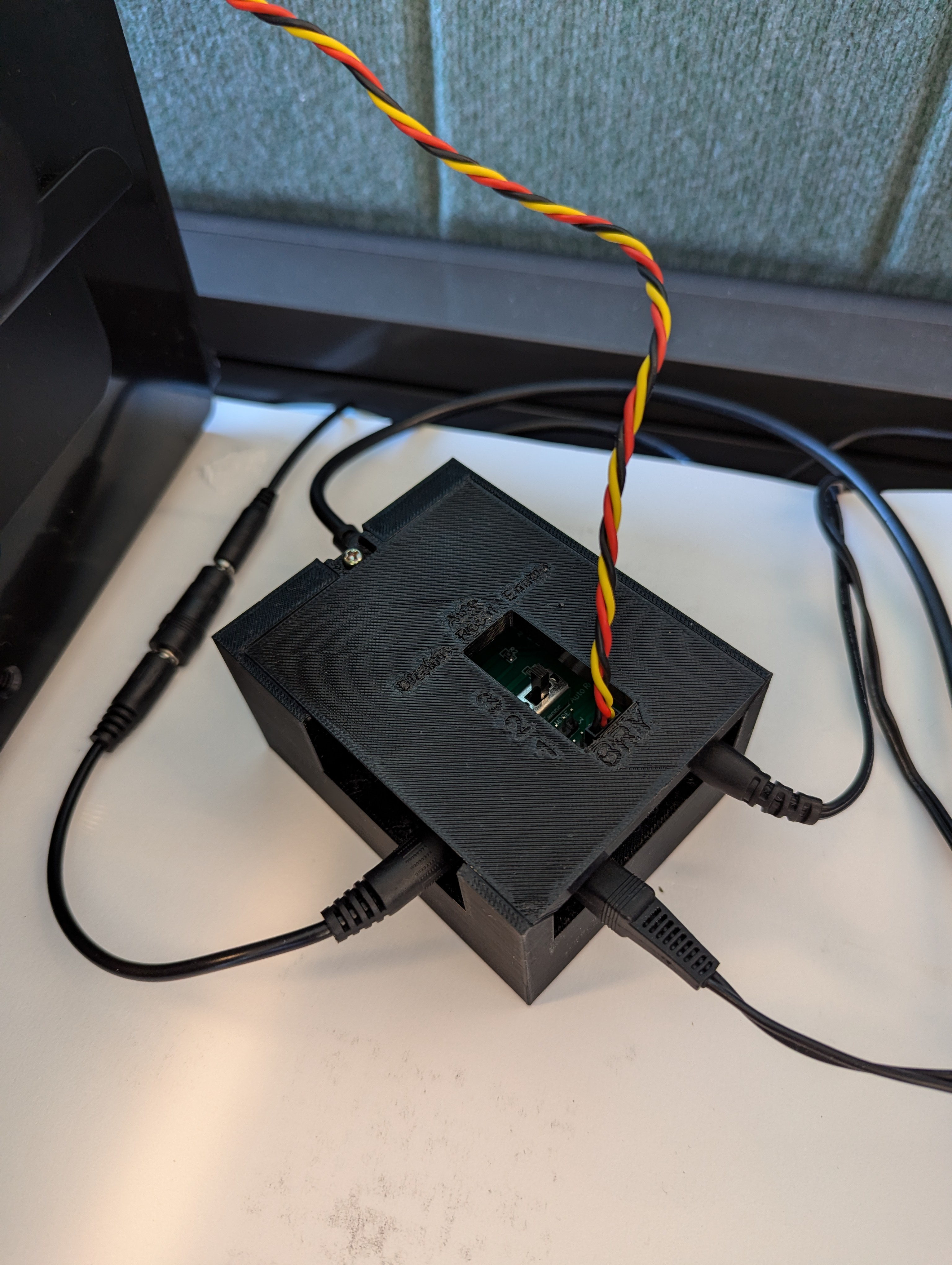
รูปที่ 24 ตัวอย่างการเชื่อมต่อตัวควบคุมแสงสว่าง Arduino Rev3ติดเทปกาวกล่องเข้าด้วยกัน แล้วขันสกรูชิ้นส่วนต่างๆ เข้าด้วยกัน (คุณอาจต้อง เจาะรูล่วงหน้าในบางชิ้นส่วน)
รูปที่ 25 แท่นทดสอบการรวมเซ็นเซอร์ที่ติดเทป
สำหรับ Android 15 ขึ้นไป ให้ทำงานร่วมกับร้านพิมพ์ในพื้นที่เพื่อพิมพ์ไฟล์ checkerboard.pdf (รวมอยู่ในไดเรกทอรี
test/sensor_fusionของโค้ดเบส) บนกระดาษขนาด 18 x 18 นิ้วที่มีรูปแบบตารางหมากรุกความกว้างของกระดาษ และติดชาร์ตบนผนังตรงข้ามกับอุปกรณ์ยึดโทรศัพท์สำหรับกล้องที่มีมุมมองแคบ เช่น กล้องเทเลโฟโต้ ให้ปรึกษา ร้านพิมพ์ในพื้นที่เพื่อสร้างเวอร์ชันของตารางหมากรุกที่ปรับขนาดตามสัดส่วน (เช่น แผนภูมิที่ปรับขนาด 50% จะพิมพ์บนกระดาษขนาด 9 x 9 นิ้ว)
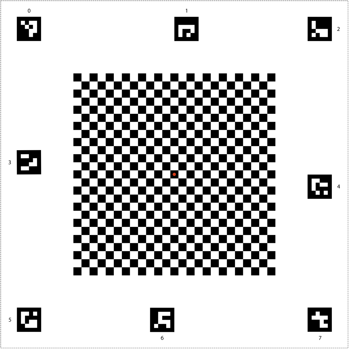
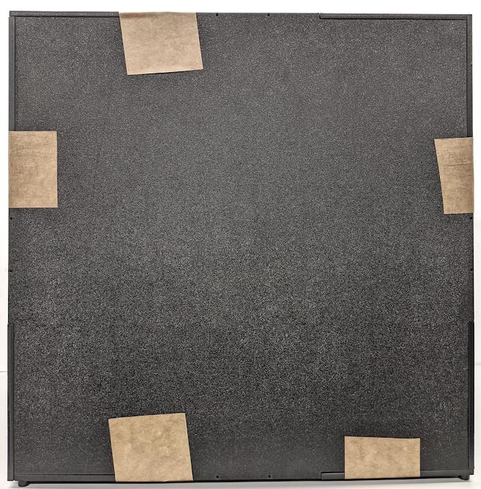
รูปที่ 26 แผนภูมิหมากรุกสำหรับ Android 15 ขึ้นไป
ตรวจสอบว่าจุดสีแดงตรงกลางตารางหมากรุกหันหน้าเข้าหากล้องโดยตรงเมื่อวางบนอุปกรณ์ติดตั้ง ดังแสดงในรูปที่ 27
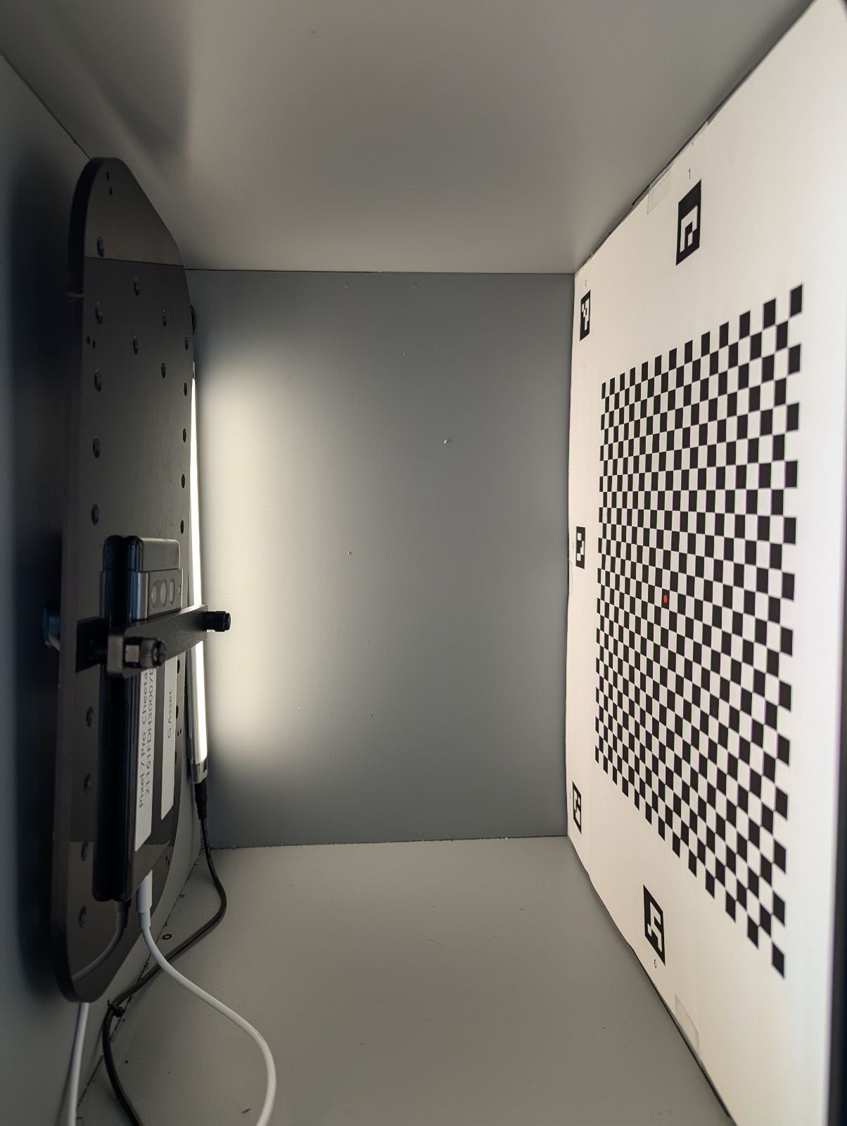
รูปที่ 27 พิมพ์และติดกระดานหมากรุกบนผนังฝั่งตรงข้ามของอุปกรณ์ยึดโทรศัพท์