
בדף הזה מוסבר איך לרכוש או להרכיב Sensor Fusion Box. התיבה Sensor Fusion Box משמשת בבדיקה CameraITS sensor_fusion ובבדיקת הסנכרון multi-camera. הוא מספק סביבת בדיקה עקבית למדידת הדיוק של חותמות הזמן של חיישנים במכשירי Android, במיוחד חיישני תמונה של מצלמות וג'ירוסקופים. הוא מורכב מרכיבי קופסת פלסטיק שנחתכים בלייזר משרטוטים של תכנון בעזרת מחשב (CAD) ומקופסת בקרת סרוו.
אפשר לקנות Sensor Fusion Box או לבנות אחד בעצמכם.
רכישה של Sensor Fusion Box
מומלץ לרכוש Sensor Fusion Box מאחד מהספקים המוסמכים הבאים.
Byte Bridge Inc.
ארה"ב: 1502 Crocker Ave, Hayward, CA 94544-7037
סין: 22F #06-08, Hongwell International Plaza Tower A, 1600 West Zhongshan Road, Xuhui, Shanghai, 200235
www.bytebt.com
androidpartner@bytebt.com
ארה"ב: +1-510-373-8899
סין: +86-400-8866-490JFT CO LTD 捷富通科技有限公司 (לשעבר MYWAY DESIGN)
סין: No. 40, Lane 22, Heai Road, Wujing Town, Minhang District, Shanghai, China
טייוואן: 4F., No. 163, Fu-Ying Road, XinZhuang District, New Taipei City 242, Taiwan
www.jftcoltd.com
service@jfttec.com or its.sales@jfttec.com
China:+86-021-64909136
Taiwan: 886-2-29089060
איך בונים קופסה למיזוג נתוני חיישנים
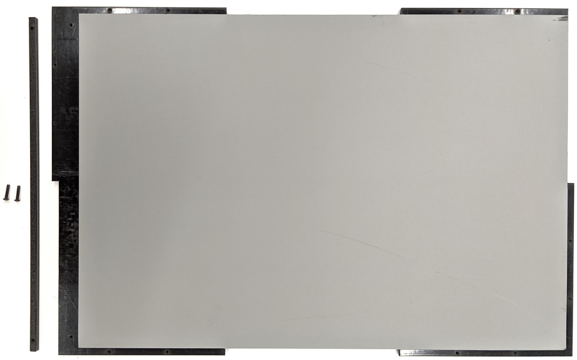
בקטע הזה מפורטות הוראות להרכבת קופסת Sensor Fusion מרכיבי אקרילוניטריל בוטאדיאן סטירן (ABS) שנחתכו בלייזר (כפי שמוצג באיור 1).
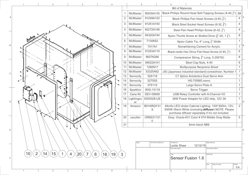
איור 1. ציור מכני של רכיבים של Sensor Fusion Box
כלים נדרשים
לפני שמתחילים, חשוב לוודא שהורדתם את השרטוטים הטכניים של Sensor Fusion Box (כלולים ב קובץ ה-ZIP של Sensor Fusion Box) ושיש לכם את הכלים הבאים:
- מברג פיליפס
- מברג עם ראש JIS
- מפתחות הקסדצימליים
- סט מקדחה
- סכין X-ACTO
- סרט דביק
שלב 1: הדבקת מדבקות ויניל
אחרי שיוצרים את רכיבי ה-ABS באמצעות חותך לייזר, מדביקים מדבקות ויניל על קופסת הפלסטיק כדי לקבל את בקרת הצבע הנכונה בחלק הפנימי של קופסת הבדיקה:
מדביקים את הוויניל על הצד החלק של ה-ABS, כמו שמוצג באיור 2. טיפים מועילים להדבקת ויניל זמינים ב-wikiHow.
חותכים את החורים הדרושים בוויניל באמצעות סכין יפנית.
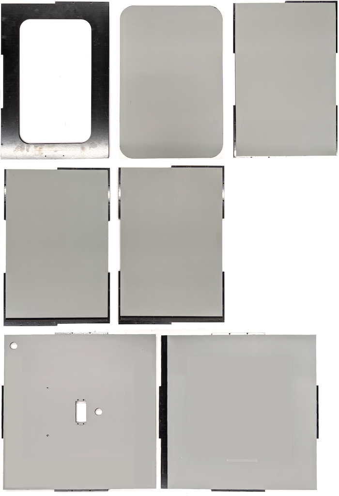
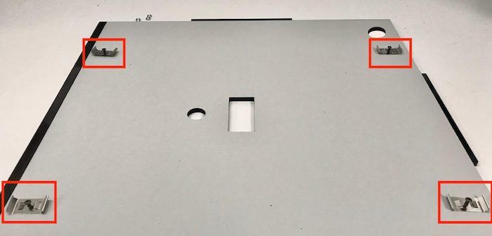
איור 2. חלקי ABS עם ויניל בצד החלק (הפנימי של הקופסה)בעזרת דבק אקרילי, מדביקים את חלקי ה-ABS העגולים לארבע הפינות של הפאנל התחתון.
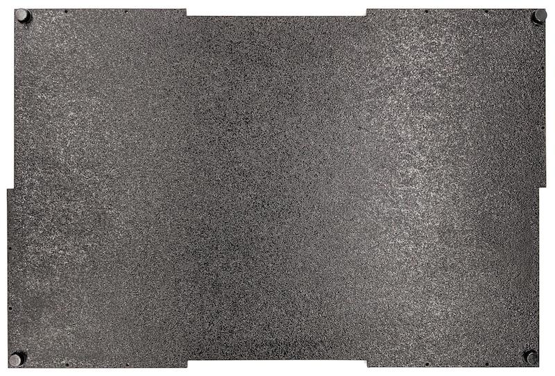
איור 3. לוח תחתון עם חלקי ABS עגולים שמוצמדים לארבע הפינות.
שלב 2: מכינים את תושבת הטלפון ומחברים את תושבת הסרוו
כדי להכין את תושבת הטלפון לחיבור לסרוו:
מקישים על 20 חורים במתקן הטלפון עם מקדח 1/4"-20.
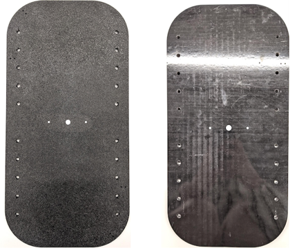
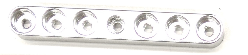
איור 4. מתקן לטלפון עם חורים מוברגיםצריך לוודא שיש לכם את החלקים הבאים: חיתוכי ABS, ברגי אגודל מניילון, אומים מניילון (לכוונון גובה הבורג אם צריך), זרוע סרוו כפולה C1 spline actobotics, ברגי 4-40 וקפיצי דחיסה.
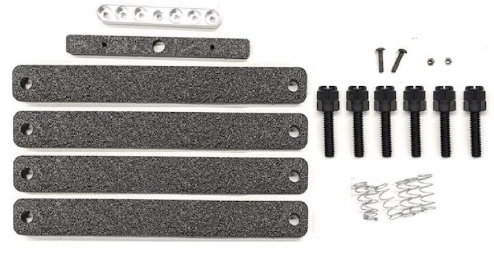
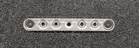
איור 5. חלקים של תושבות לטלפוניםמחברים את זרוע הסרוו לחלק האחורי של תושבת הטלפון באמצעות ברגי 4-40 ומבריגים אותם (1.2 N*m או 8.9 in*lbf). באמצעות אותם ברגים ואומים מסוג 4-40, מהדקים את החלק החתוך של מחיצת הטלפון מ-ABS בצד הקדמי של תושבת הטלפון.
איור 6. מוט בחלק האחורי של המתקן, מוברג באמצעות ברגים שמוחדרים מהחלק הקדמי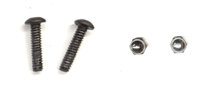
איור 7. ברגים באורך 3/4" מסוג 4-40 ואומים מכסיים מסוג 4-40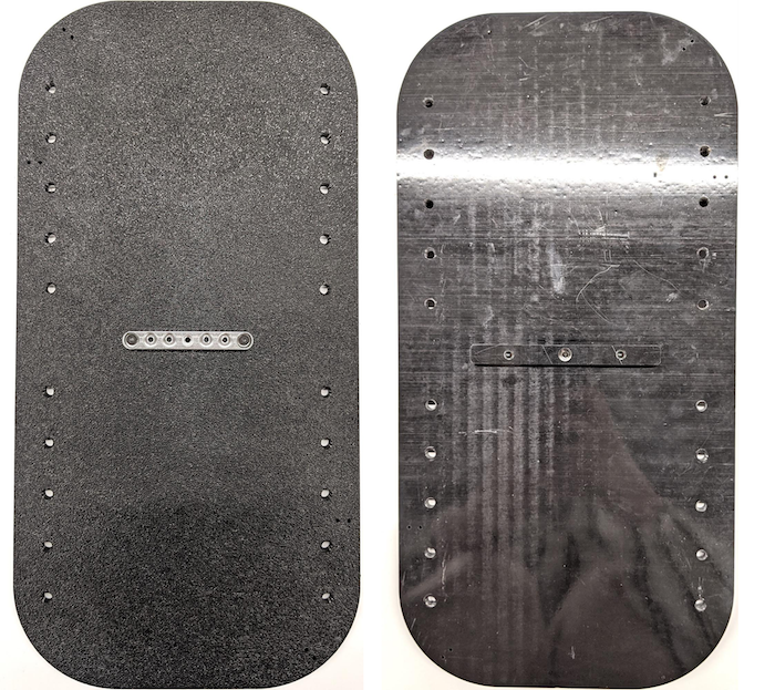
איור 8. החלק האחורי (שמאל) והחלק הקדמי (ימין) של תושבת הטלפון
שלב 3: חיבור מהדקי הטלפון
כדי לחבר את התפסים לטלפון:
גוזרים את יריעת הניאופרן לפי הצורה של מהדקי ה-ABS, אבל משאירים אותה קצרה יותר בסנטימטר אחד משני הקצוות, כמו שמוצג באיור 9. אחרי שחותכים את יריעת הניאופרן בהתאם, מצמידים את החלקים למהדקי ה-ABS החתוכים כמו באיור 8.
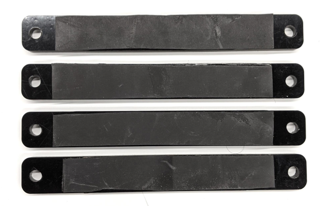
איור 9. מהדק ABS עם יריעת ניאופרןמחברים את ברגי האגודל מניילון ואת חוט הקפיץ למהדק. מוסיפים אומים מניילון כדי לקצר את אורך הבורג, לפי הצורך.
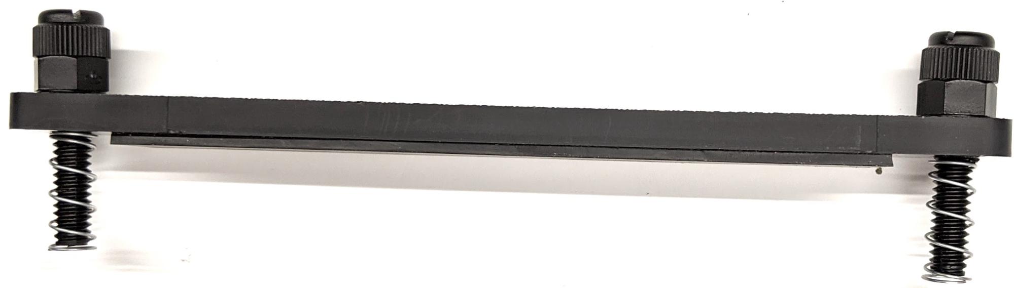
איור 10. מהדק עם יריעת ניאופרן, ברגי אגודל, אומים מניילון וחוט קפיץמבריגים את ברגי האגודל של מהדקי הטלפון לתוך החורים עם ההברגה של מתקן הטלפון, כמו שמוצג באיור 11. אפשר לשנות את המיקום של תושבות הטלפון בהתאם לגודל הטלפונים.
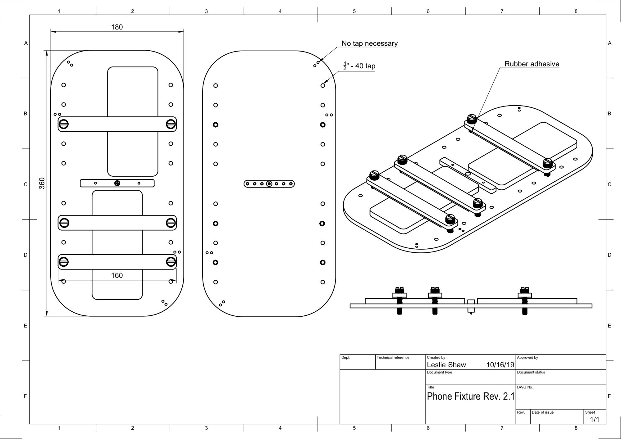
איור 11. שרטוט מכני של מתקן הטלפון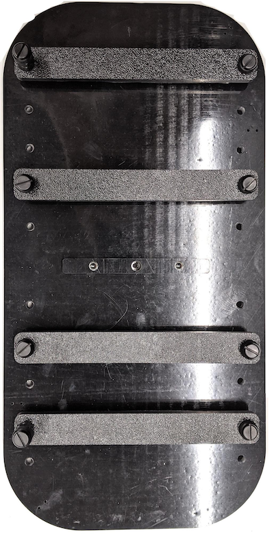
איור 12. מתקן טלפון מורכב
שלב 4: הרכבת מסילת הדלת הנפתחת
מקבעים את מסילות הפאנל הנשלף בחלק העליון והתחתון של הקופסה לכיוון החזית. איור 13 מציג 6-32 ברגים בחורים שנקדחו מראש. אפשר גם להשתמש בברגים עם הברגה עצמית.
איור 13. מסילה קבועה של חלונית נשלפת בחלק העליון והתחתון של התיבה
שלב 5: חיבור התאורה
כדי לחבר את התושבות של התאורה ואת מפזר האור:
מניחים שני חלקים של ידית אחד על השני ומבריגים אותם באמצעות ברגים 6-32 (או ברגים עם הברגה עצמית).
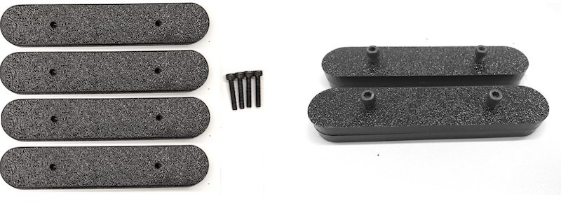
איור 14. ידיות וערכות להרכבת קופסת Sensor Fusionמכינים ארבעה ברגים, אומים ואומים בצורת בלוט 4-40 כדי לקבע את תושבת ההרכבה מקופסת התאורה לקיר של הקופסה.
איור 15. ברגים 4-40 ותושבת תאורה על הקיר הפנימי של הקופסה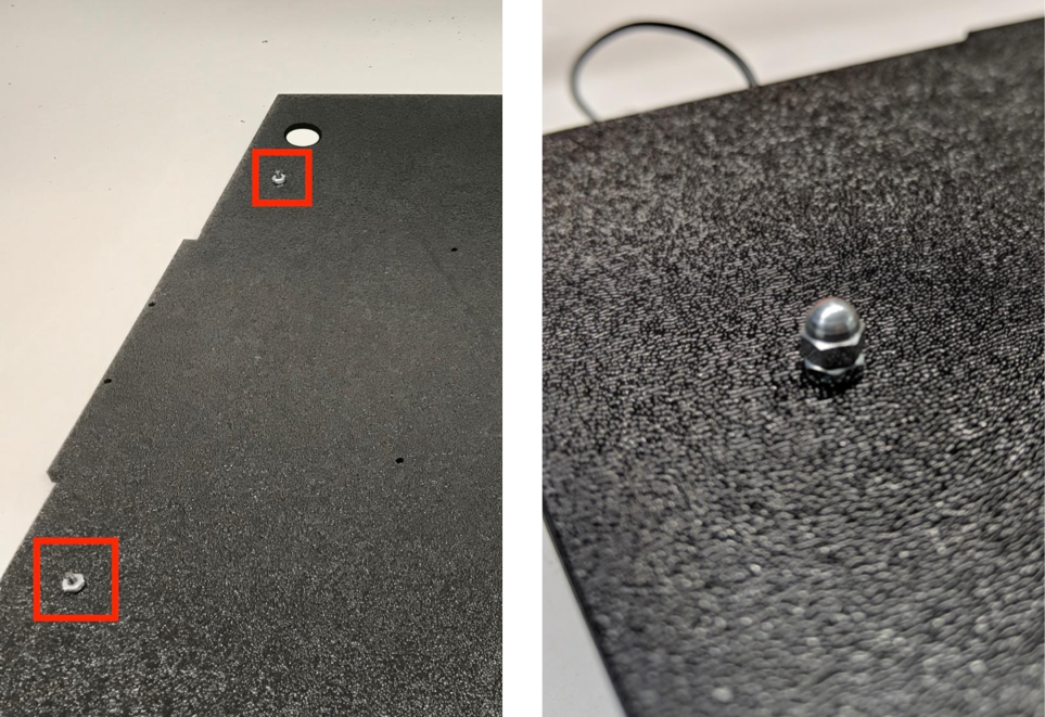
איור 16. ברגים וברגי אום שמוברגים לברגים מבחוץ של הקופסהגוזרים את מפזר האור לגודל המתאים כדי לעטוף את פסי האור (לא נדרש אם האורות מגיעים עם מפזר).
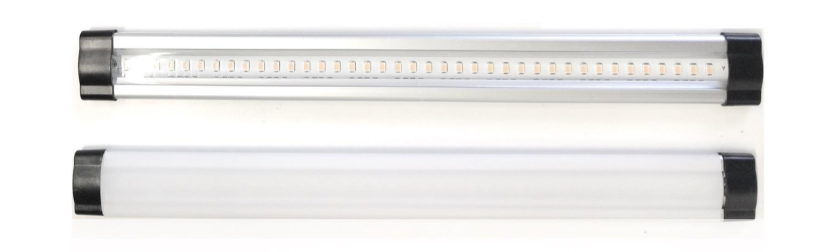
איור 17. רצועות תאורה ומפזרי אורמלפפים את מפזר האור סביב הפס ומדביקים אותו מאחור.
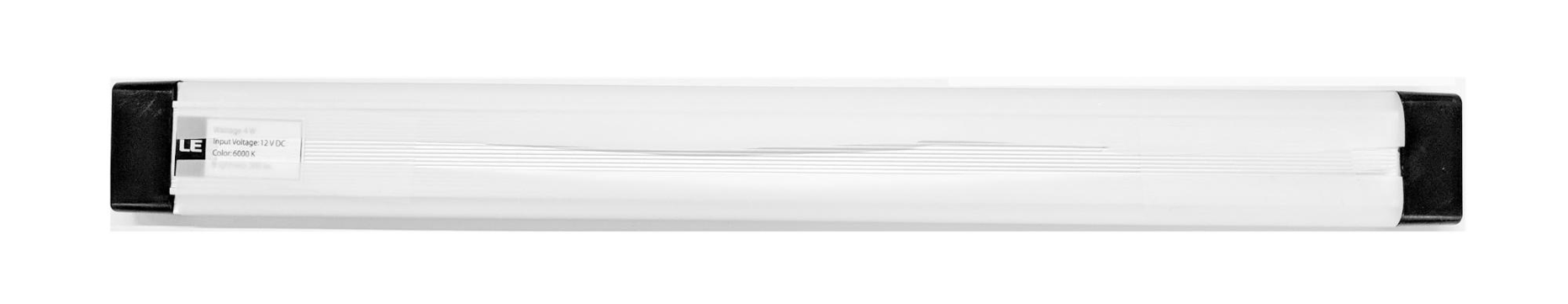
איור 18. רצועות תאורה ומפזרי אור מודבקים מאחורמצמידים את האורות לתושבות (יכול להיות שיהיה צורך להפעיל קצת כוח).
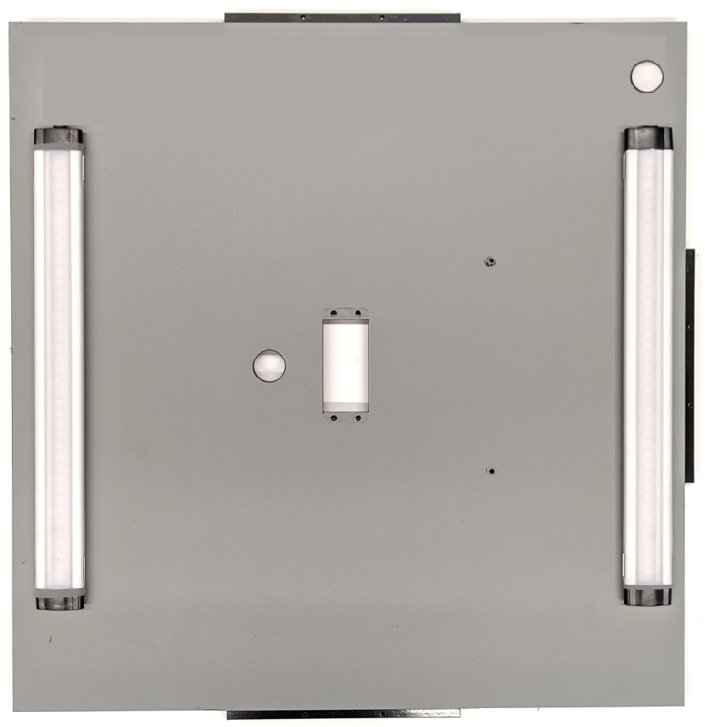
איור 19. נורות שמותקנות בסוגריים
שלב 6: מחברים את מתקן הטלפון ללוח הסרוו
כדי לחבר את מתקן הטלפון ללוח הסרוו:
מכינים ארבעה ברגי 6-32 ולוחית סרוו כדי לקבע את הסרוו לקיר. מקבעים את הסרוו לקיר הפנימי ומבריגים את הברגים מבפנים לתוך לוחית הסרוו בקיר החיצוני.
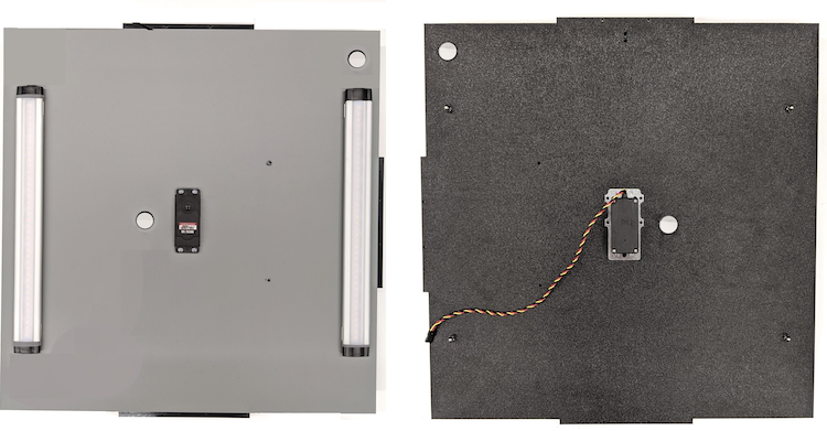
איור 20. מנוע סרוו ולוח סרוו מוחזקים במקומם באמצעות ברגי 6-32מהדקים את מתקן הטלפון לסרוו באמצעות אומים עם ניילון (דוחפים את מרכז הציר למרכז הסיבוב של הסרוו).
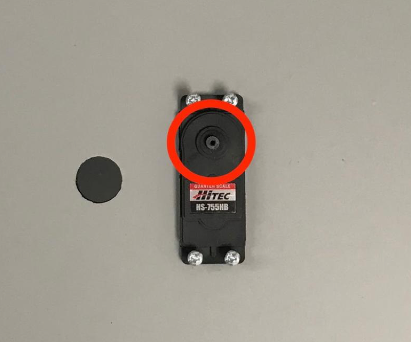
איור 21. גלגל שיניים של סרוו
בעזרת בורג הסרוו שמגיע עם הסרוו, מבריגים (1.2 N*m או 8.9 in*lbf) את מתקן הטלפון לגלגל השיניים של הסרוו דרך זרוע הסרוו.
איור 22. זרוע סרוו
שלב 7: הרכבה סופית
כדי להשלים את ההרכבה של Sensor Fusion Box:
מגרסת Android 13, מתקן הבדיקה של שילוב החיישנים מגיע עם בקר התאורה של Arduino ל-Android 13. (ב-Android 12 ומטה, ערכת החיישנים המשולבים נשלחה עם בקר Arduino בעל 6 ערוצים או עם בקר Canakit. מכשירים עם Android מגרסה 11 עד גרסה 12 תואמים לבקר Android 13, לבקר Arduino עם 6 ערוצים או לבקר Canakit). מחברים את תוסף הסרוו לכל ערוץ של בקר הסרוו, כאשר GND מתאים לחוט השחור, VCC מתאים לחוט האדום ו-SIG מתאים לחוט הצהוב.
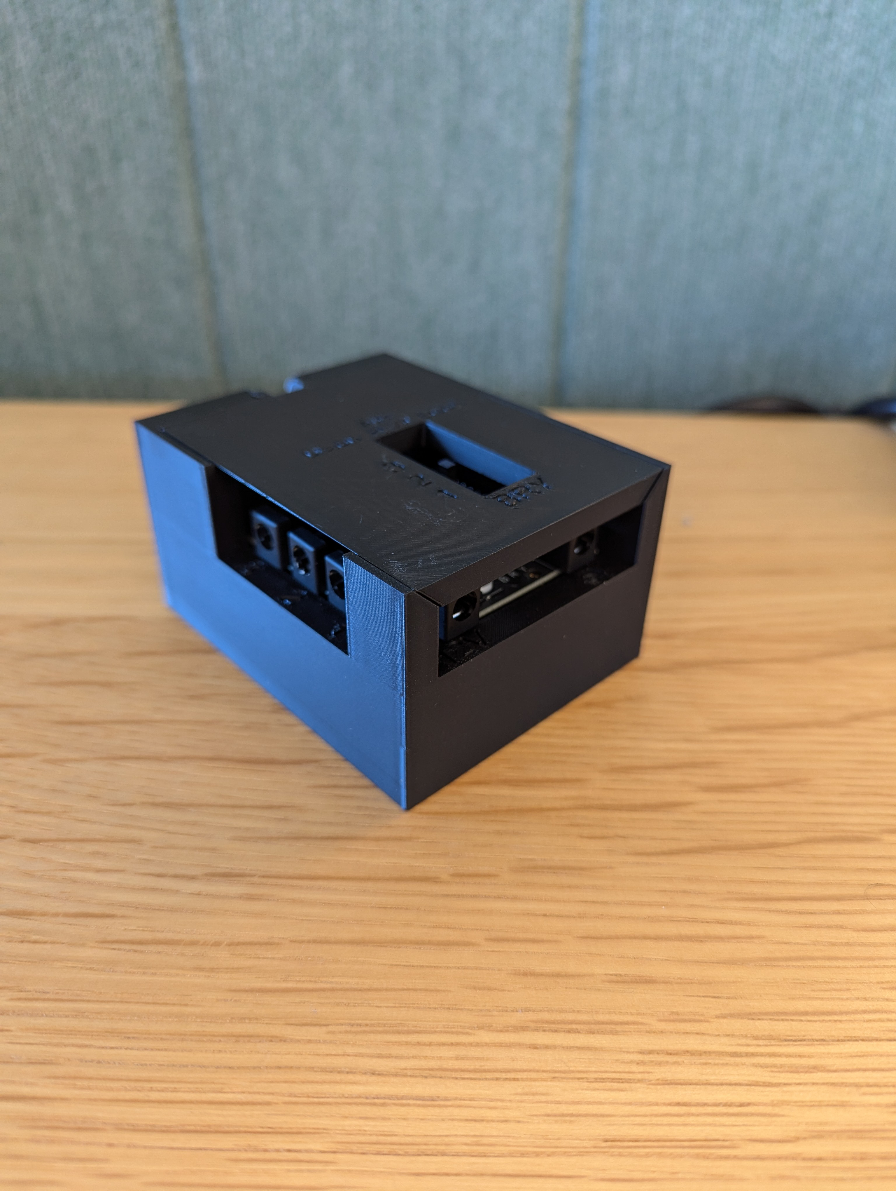
איור 23. Arduino Lighting Controller Rev3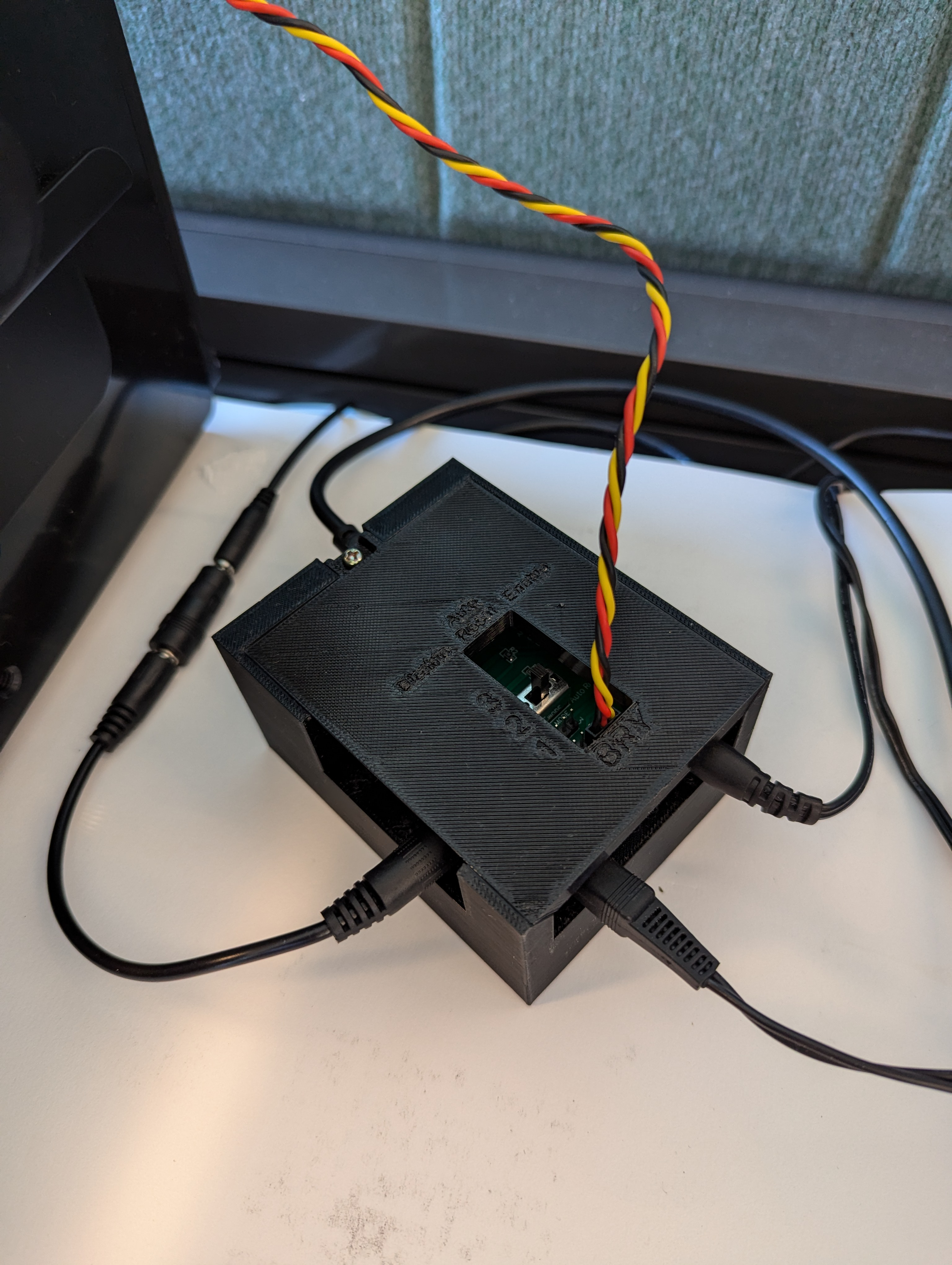
איור 24. דוגמה לחיבור של בקר תאורה Arduino Rev3מדביקים את הקופסה בעזרת סרט דביק, ואז מבריגים את החלקים (יכול להיות שיהיה צורך לקדוח מראש חורים בחלק מהחלקים).
איור 25. מכשיר בדיקה של שילוב חיישנים מודבק
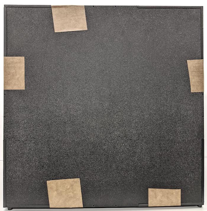
ב-Android 15 ומעלה, עובדים עם בית דפוס מקומי כדי להדפיס את הקובץ checkerboard.pdf (שנכלל בספריית
test/sensor_fusionשל בסיס הקוד) על נייר בגודל 18x18 אינץ' עם דפוס לוח השחמט ברוחב הנייר, ומדביקים את התרשים על הקיר מול מתקן הטלפון.במצלמות עם שדות ראייה קטנים יותר, כמו מצלמות טלפוטו, צריך ליצור גרסאות מותאמות של לוח השחמט בעזרת בית דפוס מקומי. (לדוגמה, תרשים שמוקטן ב-50% יודפס על נייר בגודל 9x9 אינץ').
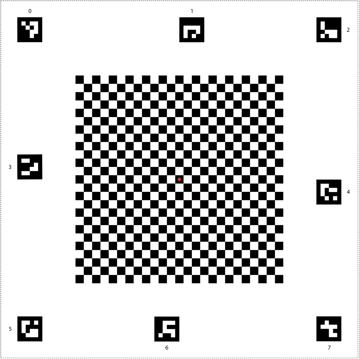
איור 26. תרשים לוח שחמט ל-Android 15 ומעלה.
מוודאים שהנקודה האדומה במרכז לוח השחמט פונה ישירות למצלמה כשהיא ממוקמת על המתקן, כמו שמוצג באיור 27.
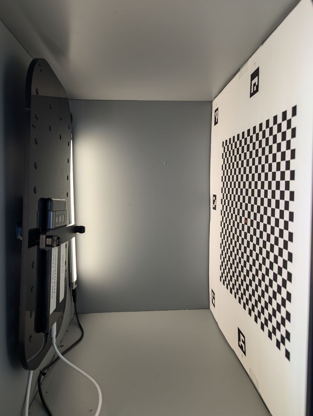
איור 27. לוח שחמט מודפס ומוצמד לקיר שממול למתקן הטלפון.