
Trang này cung cấp thông tin về cách mua hoặc lắp ráp Sensor Fusion Box. Sensor Fusion Box được dùng trong kiểm thử sensor_fusion CameraITS và kiểm thử đồng bộ hoá multi-camera. Nền tảng này cung cấp một môi trường kiểm thử nhất quán để đo độ chính xác của dấu thời gian của các cảm biến cho thiết bị Android, cụ thể là cảm biến hình ảnh của camera và con quay hồi chuyển. Thiết bị này bao gồm các thành phần hộp nhựa được cắt bằng laser từ bản vẽ thiết kế có sự trợ giúp của máy tính (CAD) và một Hộp điều khiển servo.
Bạn có thể mua Sensor Fusion Box hoặc tự tạo.
Mua Sensor Fusion Box
Bạn nên mua Sensor Fusion Box của một trong những nhà cung cấp đủ tiêu chuẩn sau.
Byte Bridge Inc.
Hoa Kỳ: 1502 Crocker Ave, Hayward, CA 94544-7037
Trung Quốc: 22F #06-08, Hongwell International Plaza Tower A, 1600 West Zhongshan Road, Xuhui, Shanghai, 200235
www.bytebt.com
androidpartner@bytebt.com
Hoa Kỳ: +1-510-373-8899
Trung Quốc: +86-400-8866-490JFT CO LTD 捷富通科技有限公司 (trước đây là MYWAY DESIGN)
Trung Quốc: No. 40, Lane 22, Heai Road, Wujing Town, Minhang District, Shanghai, China
Đài Loan: 4F., No. 163, Fu-Ying Road, XinZhuang District, New Taipei City 242, Taiwan
www.jftcoltd.com
service@jfttec.com hoặc its.sales@jfttec.com
Trung Quốc:+86-021-64909136
Đài Loan: 886-2-29089060
Xây dựng hộp kết hợp cảm biến
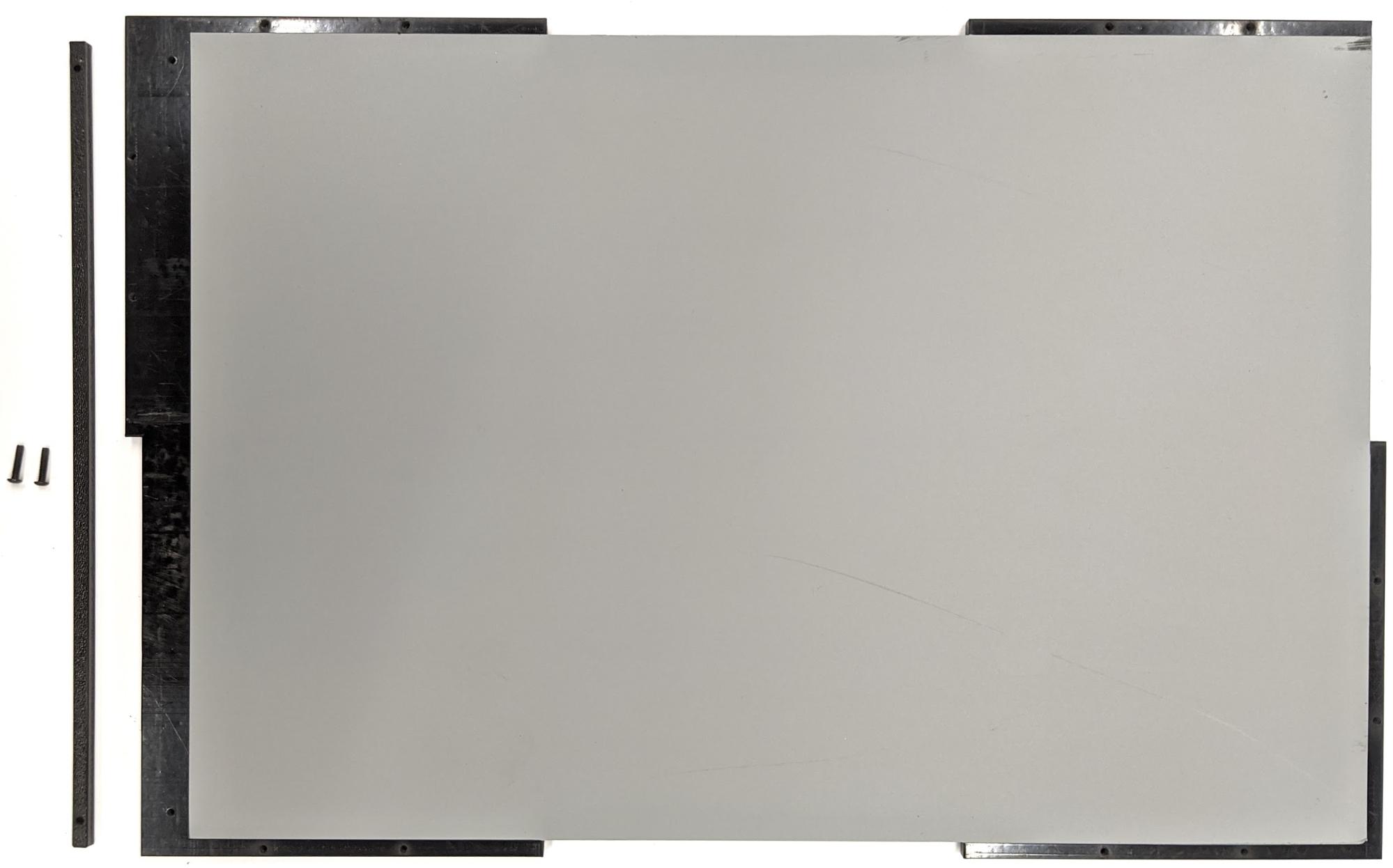
Phần này bao gồm hướng dẫn từng bước để lắp ráp một Sensor Fusion Box từ các thành phần acrylonitrile butadiene styrene (ABS) được cắt bằng laser (như trong Hình 1).
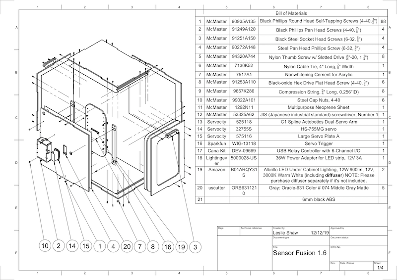
Hình 1. Bản vẽ cơ khí về các thành phần của Hộp hợp nhất cảm biến
Các công cụ bắt buộc
Trước khi bắt đầu, hãy đảm bảo bạn đã tải bản vẽ kỹ thuật cho Sensor Fusion Box xuống (có trong tệp zip Sensor Fusion Box) và có sẵn các công cụ sau:
- Tua vít đầu 4 cạnh
- Tua vít đầu JIS
- Chìa lục giác
- Bộ máy khoan điện
- Dao X-ACTO
- Băng
Bước 1: Dán miếng dán vinyl
Sau khi tạo các thành phần ABS bằng máy cắt laser, hãy dán miếng dán vinyl lên hộp nhựa để kiểm soát màu sắc phù hợp ở bên trong hộp kiểm thử:
Dán miếng nhựa vinyl lên mặt nhẵn của ABS như trong Hình 2. Để biết các mẹo hữu ích về cách dán decal, hãy tham khảo wikiHow.
Dùng dao rọc giấy để cắt các lỗ cần thiết trên tấm nhựa vinyl.
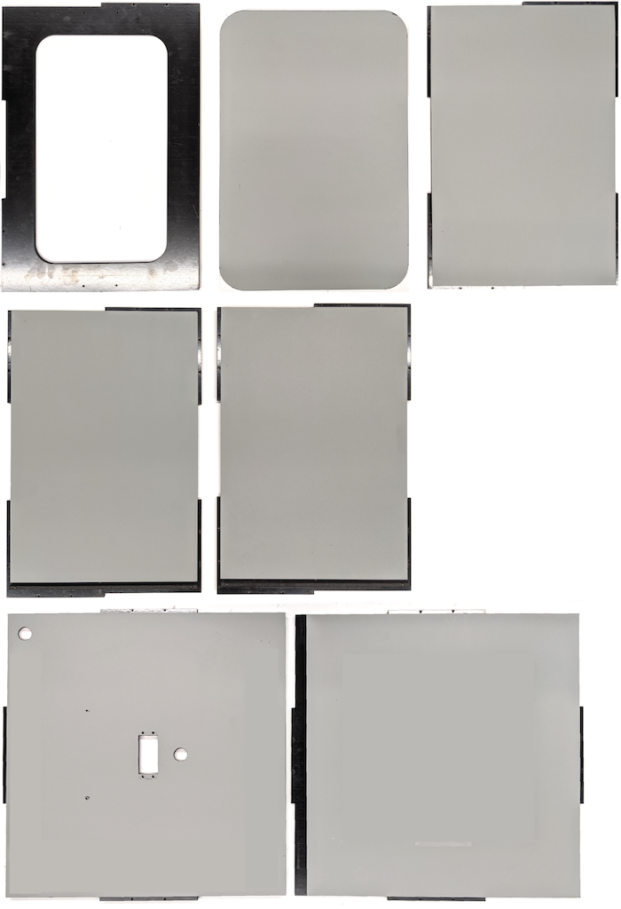
Hình 2. Các miếng ABS có lớp vinyl được dán ở mặt nhẵn (bên trong hộp)Dùng keo acrylic để dán các miếng ABS tròn vào 4 góc của bảng dưới cùng.
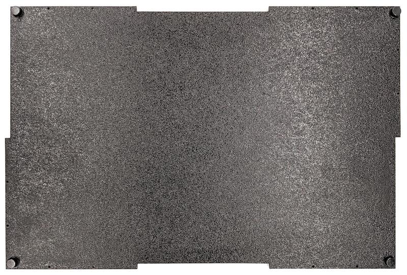
Hình 3. Tấm đáy có các miếng ABS tròn được dán vào 4 góc.
Bước 2: Chuẩn bị giá đỡ điện thoại và gắn giá đỡ servo
Cách chuẩn bị giá đỡ điện thoại để gắn vào servo:
Khoan 20 lỗ trên giá đỡ điện thoại bằng mũi khoan 1/4"-20.
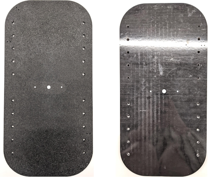
Hình 4. Giá đỡ điện thoại có các lỗ được tạo renĐảm bảo bạn có các lỗ cắt ABS, vít ngón tay bằng ni lông, đai ốc bằng ni lông (để điều chỉnh chiều cao vít nếu cần), cánh tay servo kép actobotics có rãnh C1, vít 4-40 và lò xo nén.
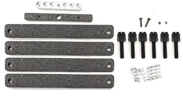
Hình 5. Linh kiện giá đỡ điện thoạiLắp các vít 4-40 và siết chặt (1,2 N*m hoặc 8,9 in*lbf) cánh tay servo vào mặt sau của giá đỡ điện thoại. Dùng cùng loại ốc vít và đai ốc 4-40, siết chặt phần chia điện thoại bằng nhựa ABS đã cắt ở mặt trước của giá đỡ điện thoại.
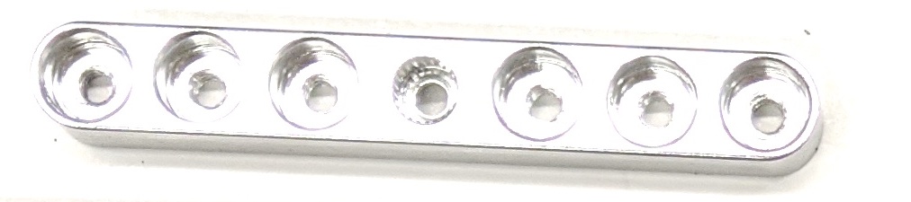
Hình 6. Trục ở mặt sau của phụ kiện, được siết chặt bằng các vít được lắp từ phía trước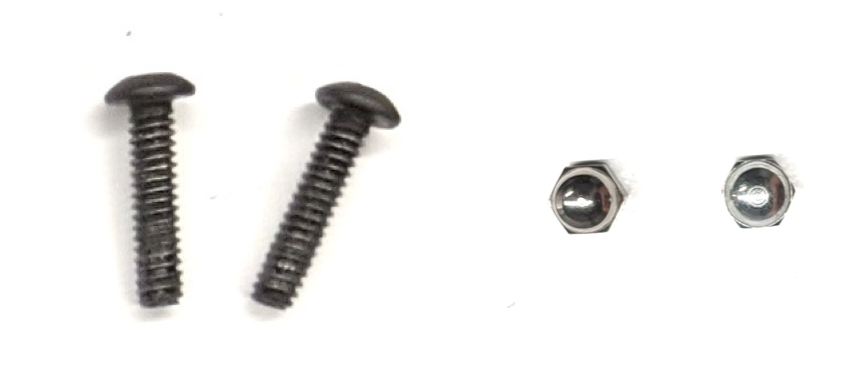
Hình 7. Vít dài 4-40, 3/4 inch và đai ốc 4-40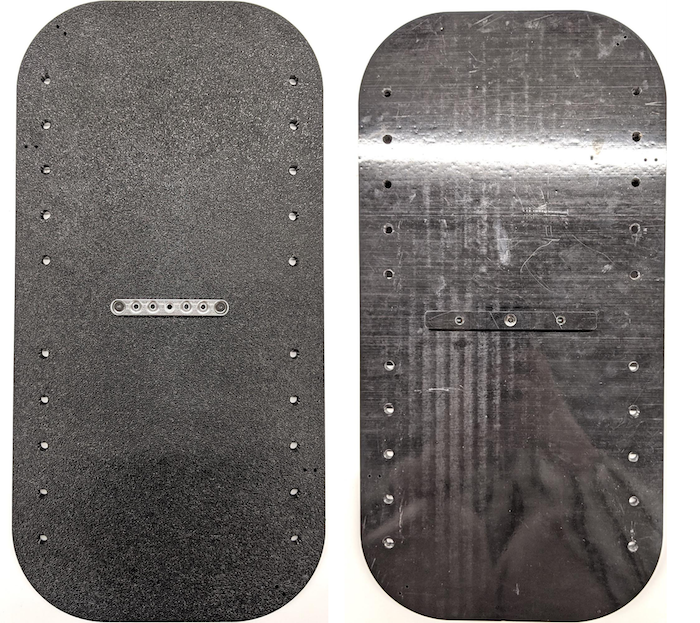
Hình 8. Mặt sau (bên trái) và mặt trước (bên phải) của giá đỡ điện thoại
Bước 3: Lắp kẹp điện thoại
Cách gắn kẹp điện thoại:
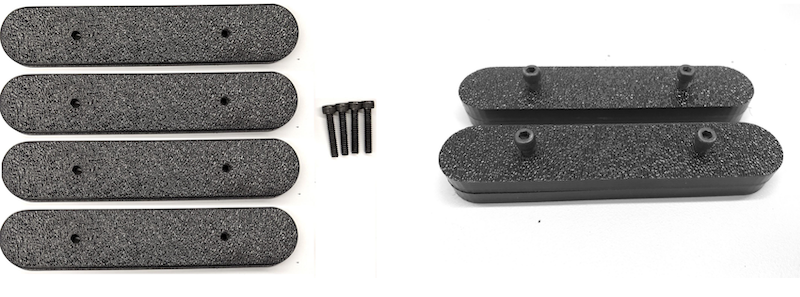
Cắt tấm cao su xốp theo hình dạng của kẹp có lỗ cắt bằng nhựa ABS, nhưng để ngắn hơn 2,5 cm ở cả hai đầu như trong Hình 9. Sau khi cắt tấm cao su xốp cho phù hợp, hãy dán các miếng vào kẹp có vết cắt ABS như trong Hình 8.
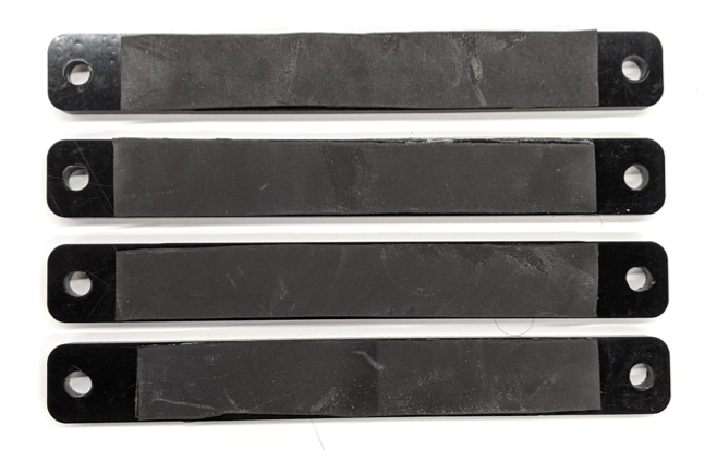
Hình 9. Kẹp ABS có tấm cao su tổng hợp được áp dụngGắn vít vặn bằng nylon và dây lò xo vào kẹp. Thêm đai ốc nylon để giảm chiều dài của vít, nếu cần.
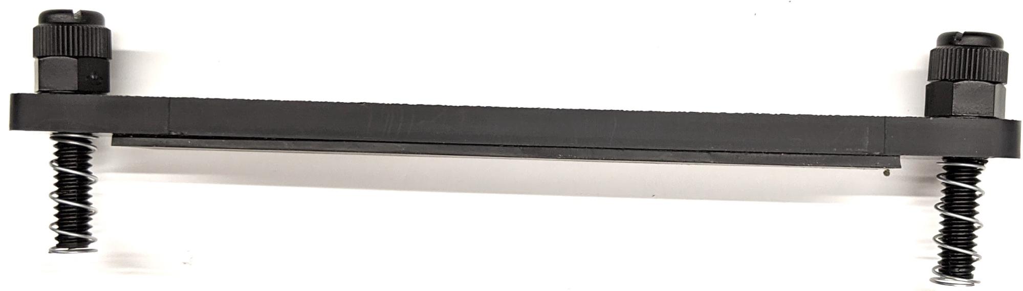
Hình 10. Kẹp có tấm cao su tổng hợp, vít ngón tay, đai ốc nylon và dây lò xoVặn các vít có núm của kẹp điện thoại vào các lỗ có ren của giá đỡ điện thoại như trong Hình 11. Bạn có thể điều chỉnh vị trí của giá đỡ điện thoại tuỳ thuộc vào kích thước của điện thoại.
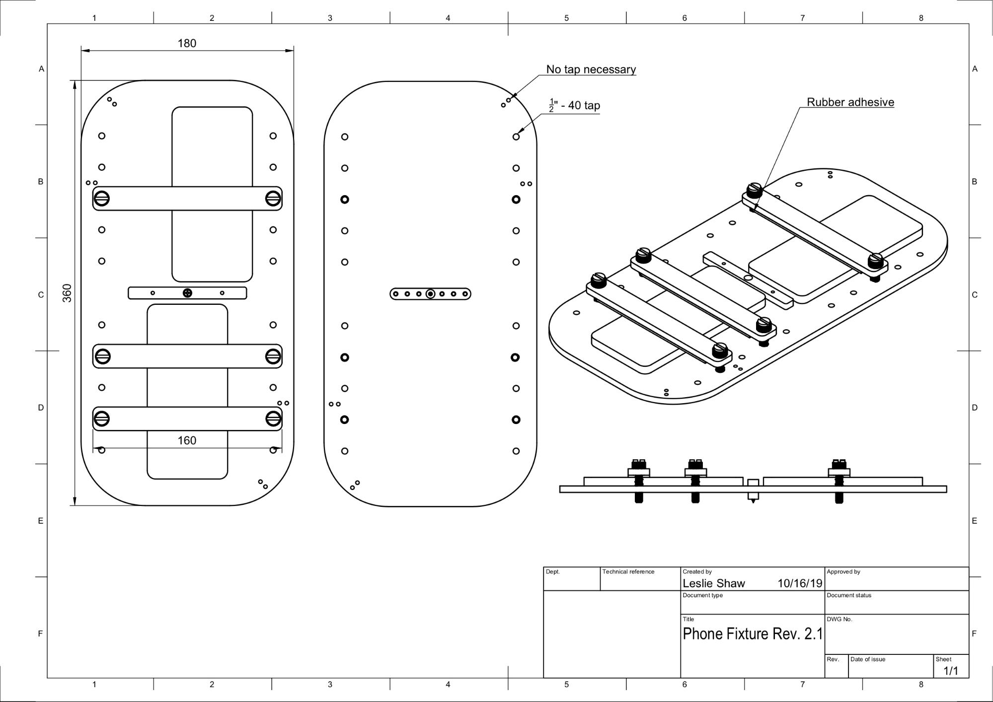
Hình 11. Bản vẽ cơ khí của giá đỡ điện thoại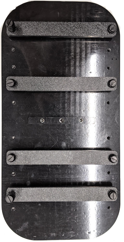
Hình 12. Giá đỡ điện thoại đã lắp ráp
Bước 4: Lắp ráp ray cửa trượt
Cố định các thanh trượt của bảng điều khiển ở phía trên và phía dưới hộp về phía trước. Hình 13 cho thấy các vít 6-32 trên các lỗ được tạo ren trước. Ngoài ra, bạn có thể dùng vít tự khoan.
Hình 13. Thanh bảng điều khiển trượt cố định ở trên cùng và dưới cùng của hộp
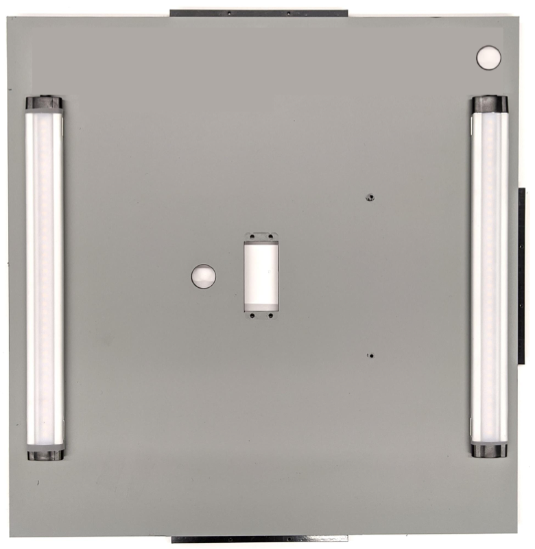
Bước 5: Lắp đèn
Cách gắn giá đỡ đèn và bộ khuếch tán:
Xếp chồng hai miếng tay cầm lên nhau rồi lắp ráp chúng bằng vít 6-32 (hoặc dùng vít tự khoan).
Hình 14. Các bộ phận tay cầm và cụm Hộp hợp nhất cảm biếnChuẩn bị 4 vít 4-40, đai ốc và đai ốc hình quả đấu để cố định giá đỡ từ bộ đèn vào thành hộp.
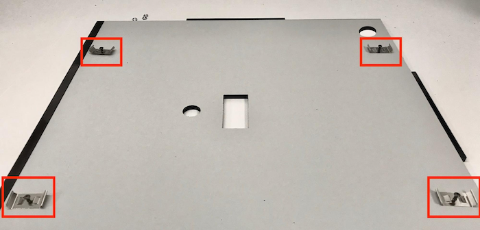
Hình 15. Vít 4-40 và giá đỡ đèn trên vách trong của hộp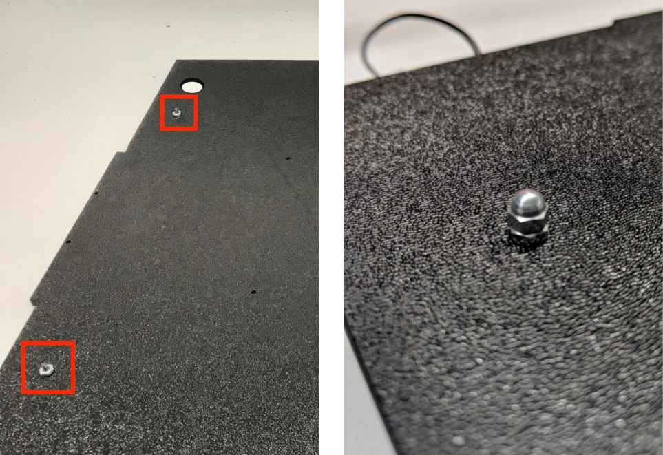
Hình 16. Bu lông và bu lông đầu tròn được gắn vào các vít từ bên ngoài hộpCắt tấm khuếch tán ánh sáng thành kích thước phù hợp để bọc dải đèn (không bắt buộc nếu đèn có tấm khuếch tán).
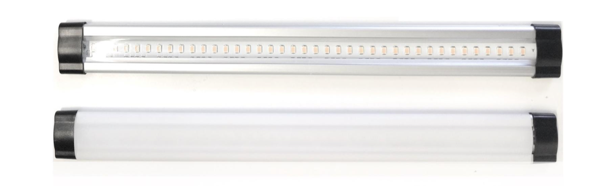
Hình 17. Dải đèn và bộ khuếch tán ánh sángQuấn tấm khuếch tán ánh sáng quanh dải đèn rồi dán băng dính ở mặt sau.
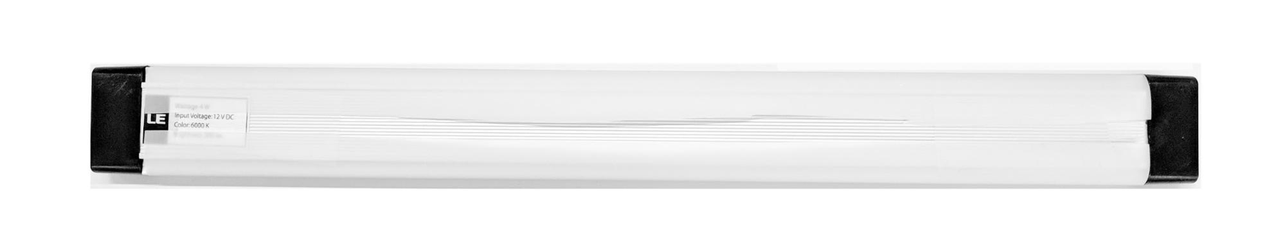
Hình 18. Dải đèn và bộ khuếch tán ánh sáng được dán từ phía sauLắp đèn vào giá đỡ (có thể sẽ hơi khó lắp).
Hình 19. Đèn được gắn trong giá đỡ
Bước 6: Gắn giá đỡ điện thoại vào tấm servo
Cách gắn giá đỡ điện thoại vào tấm servo:
Chuẩn bị 4 vít 6-32 và một tấm servo để cố định servo vào tường. Cố định servo vào tường bên trong và bắt vít từ bên trong vào tấm servo trên tường bên ngoài.
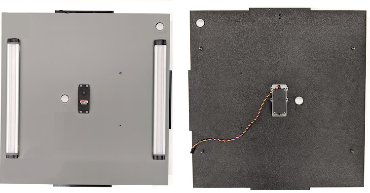
Hình 20. Động cơ servo và tấm servo được giữ cố định bằng vít 6-32Cố định giá đỡ điện thoại vào servo bằng nylock (đẩy tâm trục vào tâm quay của servo).
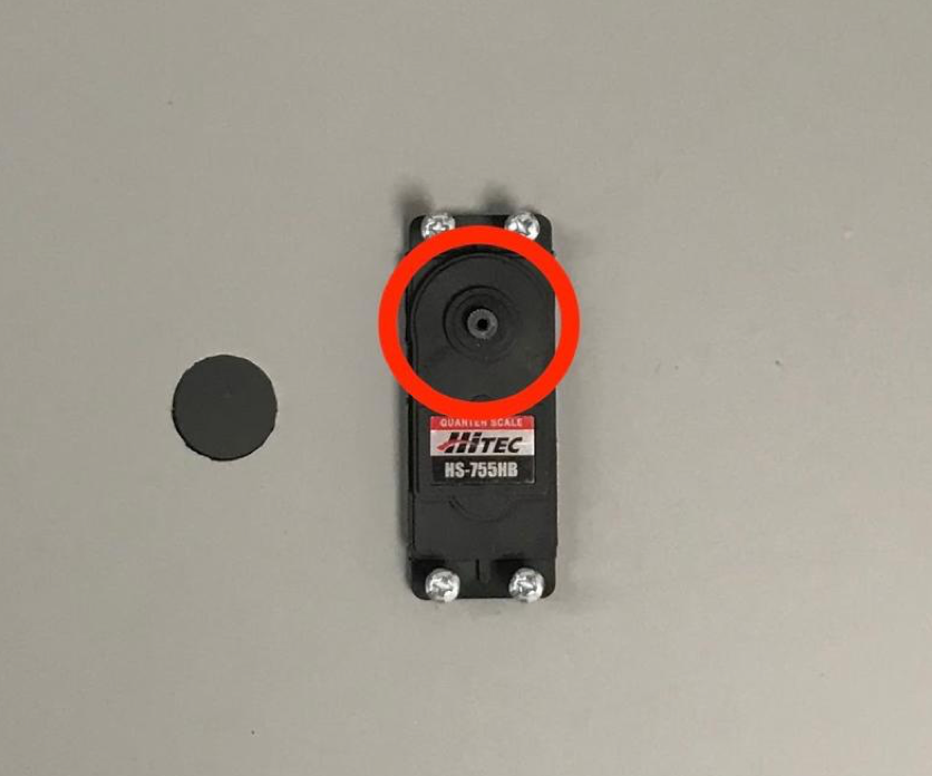
Hình 21. Bánh răng servo
Dùng vít servo đi kèm với servo, vặn (1,2 N*m hoặc 8,9 in*lbf) giá đỡ điện thoại vào bánh răng servo thông qua cánh tay servo.
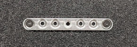
Hình 22. Cánh tay servo
Bước 7: Lắp ráp lần cuối
Cách hoàn tất việc lắp ráp Hộp kết hợp cảm biến:
Từ Android 13, giàn kiểm thử hợp nhất cảm biến sẽ đi kèm với Bộ điều khiển ánh sáng Arduino trên Android 13. (Trong Android 12 trở xuống, giàn hợp nhất cảm biến đi kèm với bộ điều khiển Arduino 6 kênh hoặc bộ điều khiển Canakit. Các thiết bị chạy Android 11 đến Android 12 đều tương thích với bộ điều khiển Android 13, bộ điều khiển Arduino 6 kênh hoặc bộ điều khiển Canakit.) Kết nối phần mở rộng servo với bất kỳ kênh nào của bộ điều khiển servo, trong đó GND tương ứng với dây màu đen, VCC tương ứng với dây màu đỏ và SIG tương ứng với dây màu vàng.
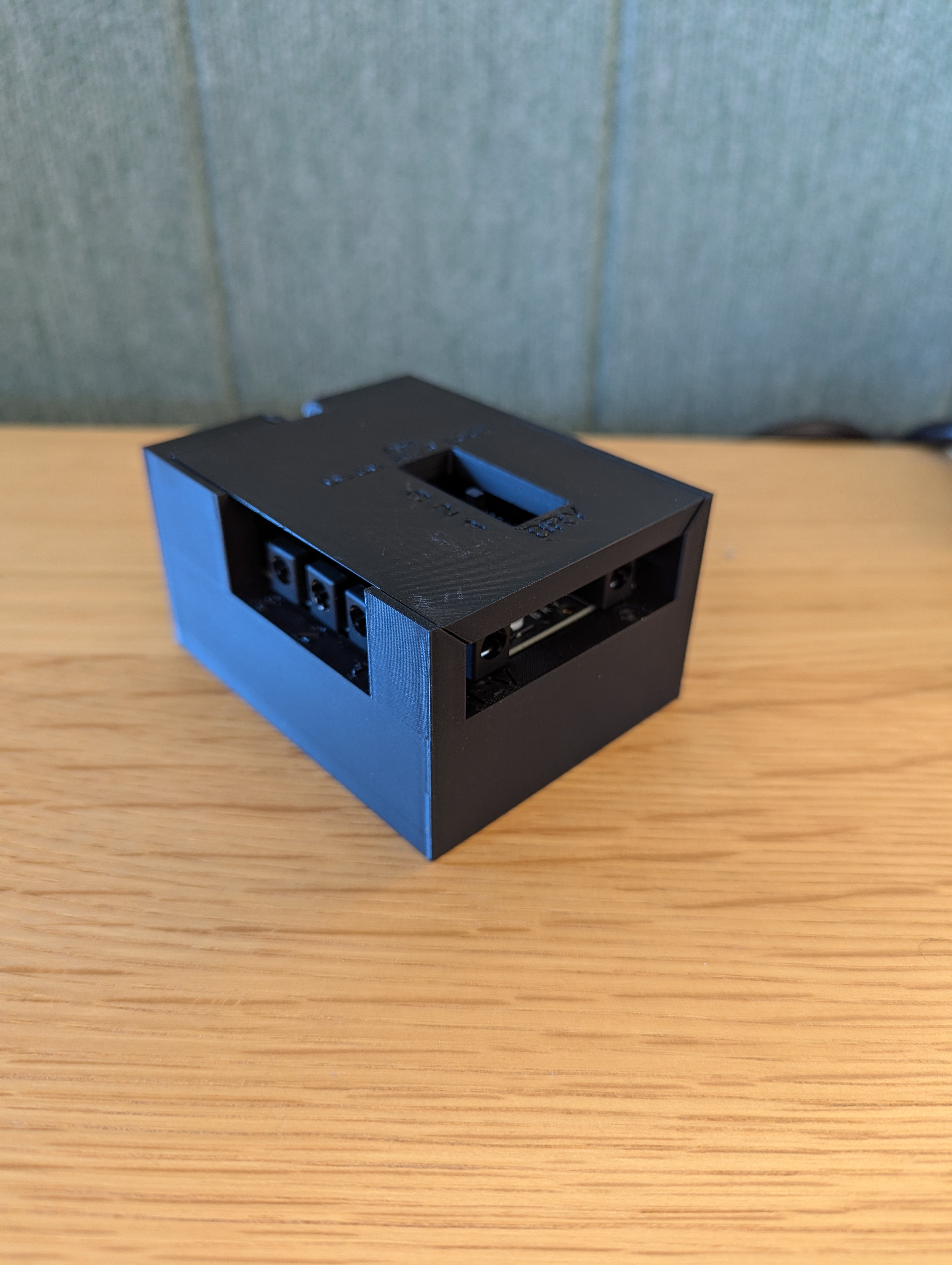
Hình 23. Bộ điều khiển ánh sáng Arduino Rev3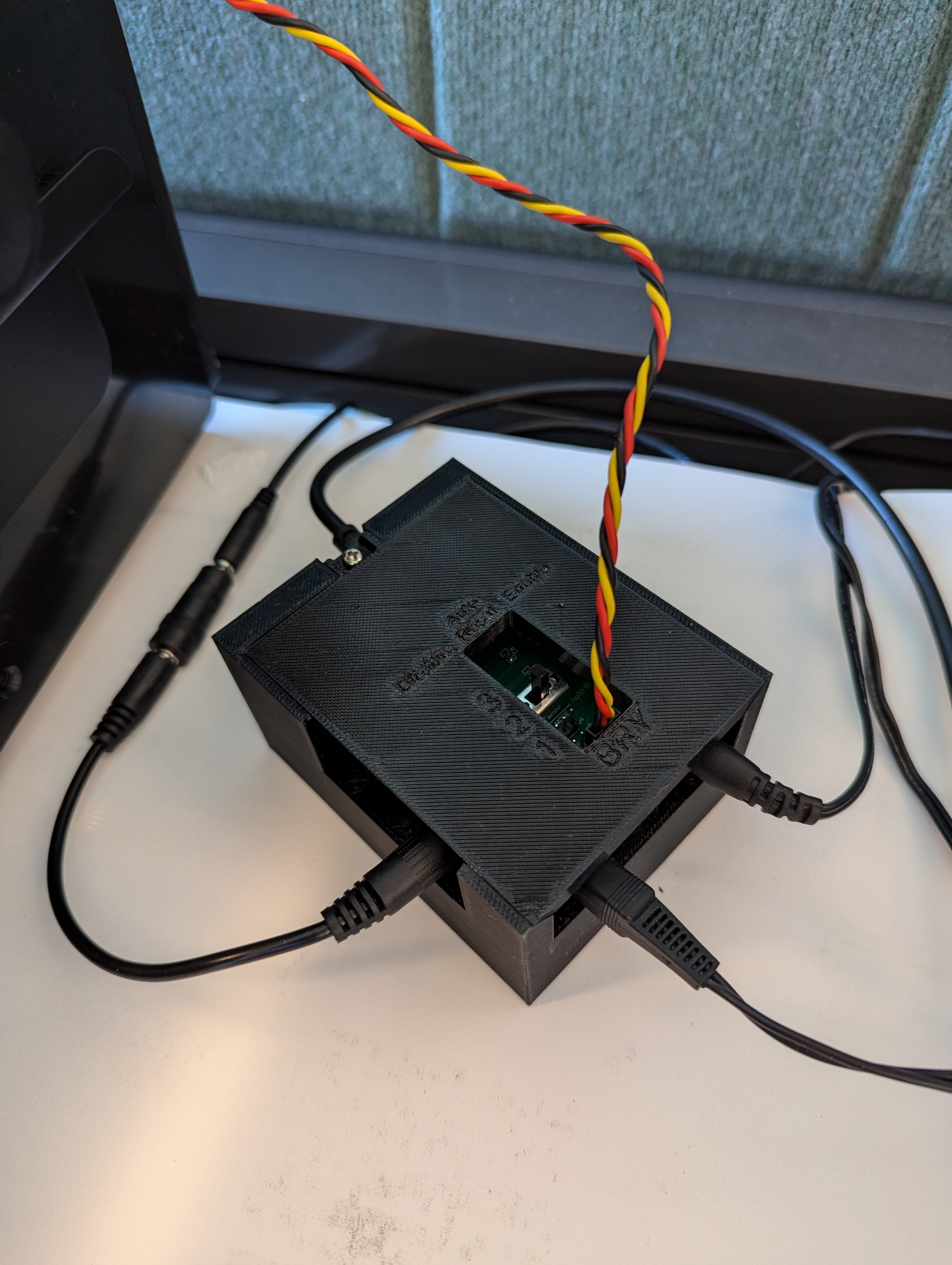
Hình 24. Mẫu kết nối Bộ điều khiển đèn Arduino Rev3Dán hộp lại với nhau, sau đó vặn các bộ phận lại với nhau (bạn có thể cần khoan trước các lỗ ở một số bộ phận).
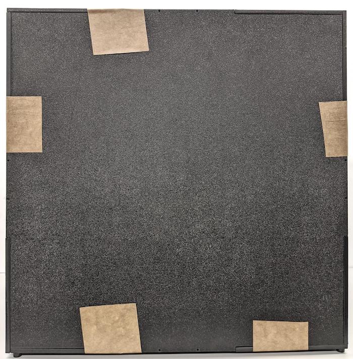
Hình 25. Thiết bị kiểm thử kết hợp cảm biến được dán băng dính
Đối với Android 15 trở lên, hãy hợp tác với cửa hàng in ấn tại địa phương để in tệp checkerboard.pdf (có trong thư mục
test/sensor_fusioncủa cơ sở mã) trên giấy có kích thước 18 x 18 inch với mẫu bàn cờ có chiều rộng bằng chiều rộng của giấy, đồng thời dán biểu đồ lên tường đối diện với giá đỡ điện thoại.Đối với những camera có trường nhìn nhỏ hơn, chẳng hạn như camera tele, hãy hợp tác với cửa hàng in địa phương để tạo các phiên bản tỷ lệ của bảng kiểm tra. (Ví dụ: biểu đồ được thu nhỏ 50% sẽ được in trên giấy có kích thước 9 x 9 inch.)
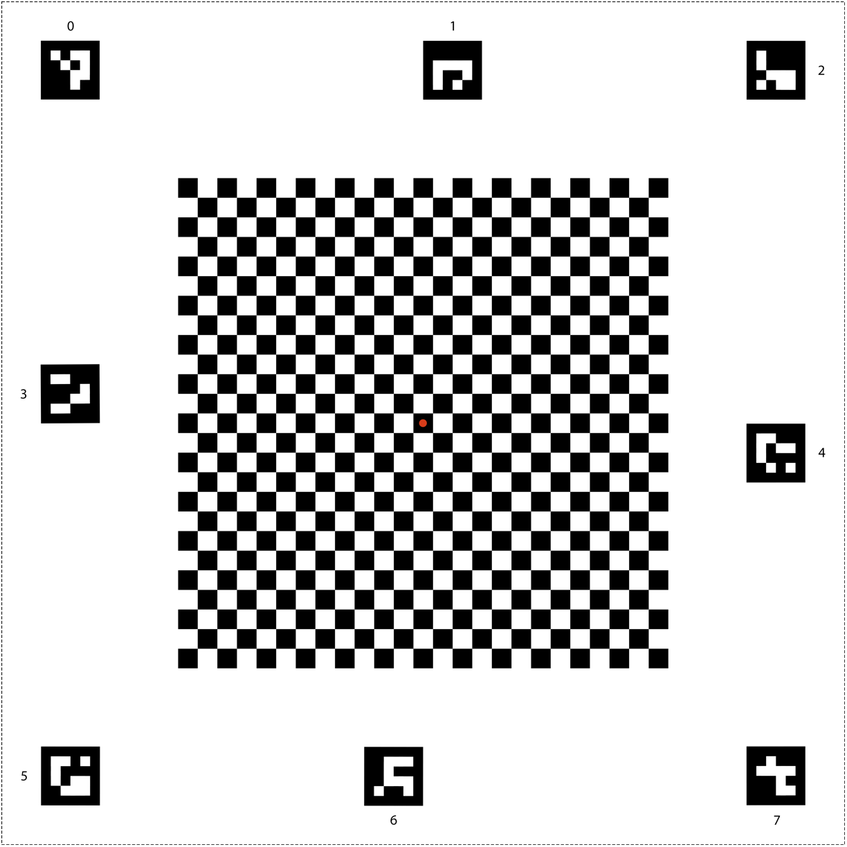
Hình 26. Biểu đồ bàn cờ cho Android 15 trở lên.
Đảm bảo chấm đỏ ở giữa bàn cờ hướng thẳng vào camera khi đặt trên giá đỡ, như minh hoạ trong Hình 27.
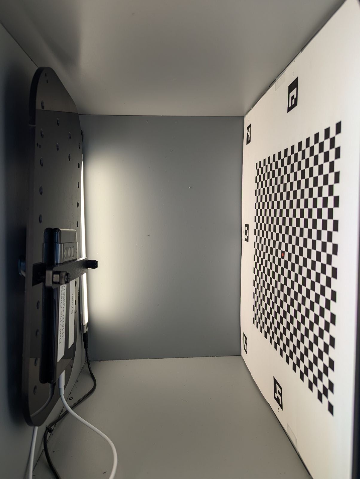
Hình 27. Bảng kẻ ô được in và dán vào bức tường đối diện của giá đỡ điện thoại.