2025 年 3 月 27 日より、AOSP のビルドとコントリビューションには aosp-main
ではなく android-latest-release
を使用することをおすすめします。詳細については、AOSP の変更をご覧ください。
Sensor Fusion Box の詳細
コレクションでコンテンツを整理
必要に応じて、コンテンツの保存と分類を行います。
このページでは、Sensor Fusion Box の購入と組み立ての方法について説明します。Sensor Fusion Box は、CameraITS sensor_fusion
テストと multi-camera
同期テストで使用されます。これにより、Android デバイスのセンサー(特にカメラ イメージ センサーとジャイロスコープ)のタイムスタンプ精度を測定する一貫したテスト環境が提供されます。Sensor Fusion Box は、CAD 図面からレーザーカットされたプラスチック製の箱型部品とサーボ制御ボックスで構成されています。
Sensor Fusion Box は、購入することも、自分で製作することもできます。
Sensor Fusion Box の購入
次の認定ベンダーから Sensor Fusion Box を購入することをおすすめします。
Byte Bridge Inc.
USA: 1502 Crocker Ave, Hayward, CA 94544-7037
China: 22F #06-08, Hongwell International Plaza Tower A,
1600 West Zhongshan Road, Xuhui, Shanghai, 200235
www.bytebt.com
androidpartner@bytebt.com
USA: +1-510-373-8899
China: +86-400-8866-490
JFT CO LTD 捷富通科技有限公司(旧社名: MYWAY DESIGN)
China: No. 40, Lane 22, Heai Road, Wujing Town, Minhang District, Shanghai, China
Taiwan: 4F., No. 163, Fu-Ying Road, XinZhuang District, New Taipei City 242, Taiwan
www.jftcoltd.com
service@jfttec.com or its.sales@jfttec.com
China: +86-021-64909136
Taiwan: 886-2-29089060
Sensor Fusion Box の製作
このセクションでは、レーザーカットされたアクリロニトリル ブタジエン スチレン(ABS)製の部品(図 1)から Sensor Fusion Box を組み立てる手順を説明します。
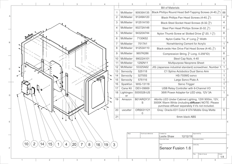
図 1. Sensor Fusion Box の部品の機械製図
始める前に、Sensor Fusion Box の技術図面(Sensor Fusion Box の ZIP ファイルに含まれています)をダウンロードし、以下の工具を用意します。
- プラス ドライバー
- JIS ねじ用ドライバー
- 六角レンチ
- 電動ドリルセット
- カッターナイフ
- テープ
ステップ 1: ビニールのステッカーを貼り付ける
レーザー カッターで ABS 部品を作成したら、テストボックス内部の色彩を適切に管理するために、ビニールのステッカーをプラスチックの箱に貼り付けます。
図 2 のように、ABS の滑らかな面にビニールを貼り付けます。ビニールを貼り付ける方法については、wikiHow を参考にしてください。
必要な穴をビニールにカッターナイフで開けます。
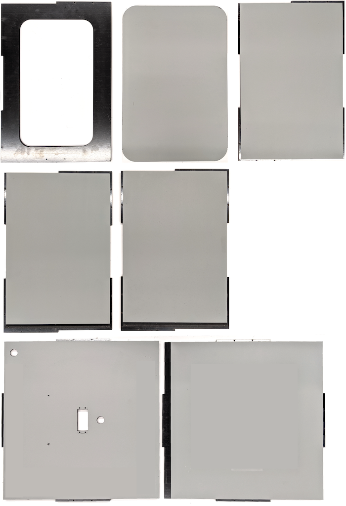
図 2. 滑らかな面(箱の内側)にビニールを貼り付けた ABS 部品
アクリル製の接着剤を使って、丸い ABS 部品を底部パネルの四隅に接着します。
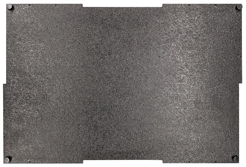
図 3. 丸い ABS 部品を四隅に接着した底部パネル
ステップ 2: スマートフォン マウントを準備し、サーボマウントを取り付ける
次のようにして、スマートフォン マウントを準備してサーボに取り付けます。
1/4 インチ - 20 のドリルビットを使ってスマートフォン固定具にねじ穴を 20 個切ります。
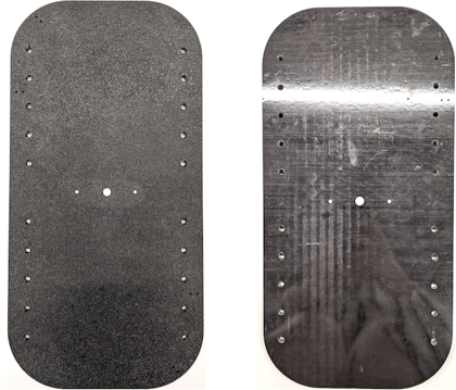
図 4. ねじ穴を切ったスマートフォン固定具
ABS の切り出し、ナイロンのつまみねじ、ナイロンのナット(必要に応じてねじの高さを調整するため)、C1 スプラインの Actobotics デュアルサーボ アーム、4-40 ねじ、圧縮ばねがあることを確認します。
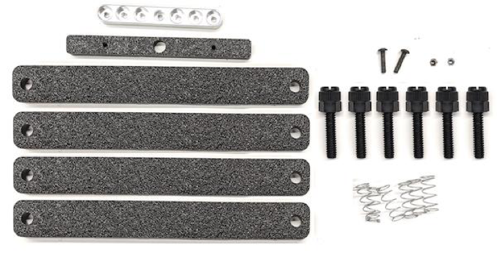
図 5. スマートフォン マウントの部品
4-40 ねじでスマートフォン マウントの背面にサーボアームを固定します(1.2 N*m または 8.9 in*lbf)。同じねじと 4-40 のキャップナットで、スマートフォン マウント前面にスマートフォン仕切りの ABS の切り出しを固定します。

図 6. 前面からねじ止めされた固定具背面のシャフト
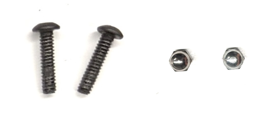
図 7. 4-40、長さ 3/4 インチのねじと 4-40 キャップナット
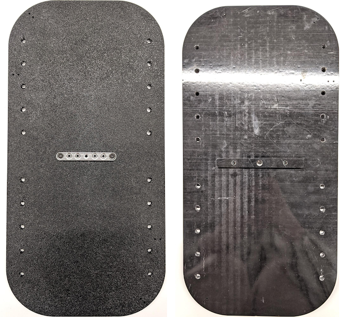
図 8. スマートフォン マウントの背面(左)と前面(右)
ステップ 3: スマートフォン クランプを取り付ける
次のようにして、スマートフォン クランプを取り付けます。
ABS の切り出しのクランプの形状に従って、ネオプレン シートをカットします。ただし、図 9 のように両端から 1 インチ(25 mm)は残します。ネオプレン シートをカットしたら、図 8 のように ABS の切り出しのクランプに部品を取り付けます。
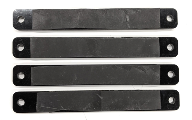
図 9. ネオプレン シートを貼った ABS のクランプ
ナイロンつまみねじと圧縮ばねをクランプに取り付けます。必要に応じて、ナイロンナットを追加してねじ長を短くします。

図 10. ネオプレン シート、つまみねじ、ナイロンナット、圧縮ばねを取り付けたクランプ
図 11 のように、スマートフォン固定具のねじ穴にスマートフォン クランプのつまみねじを締め付けます。スマートフォン マウントの位置は、スマートフォンのサイズに応じて調整できます。
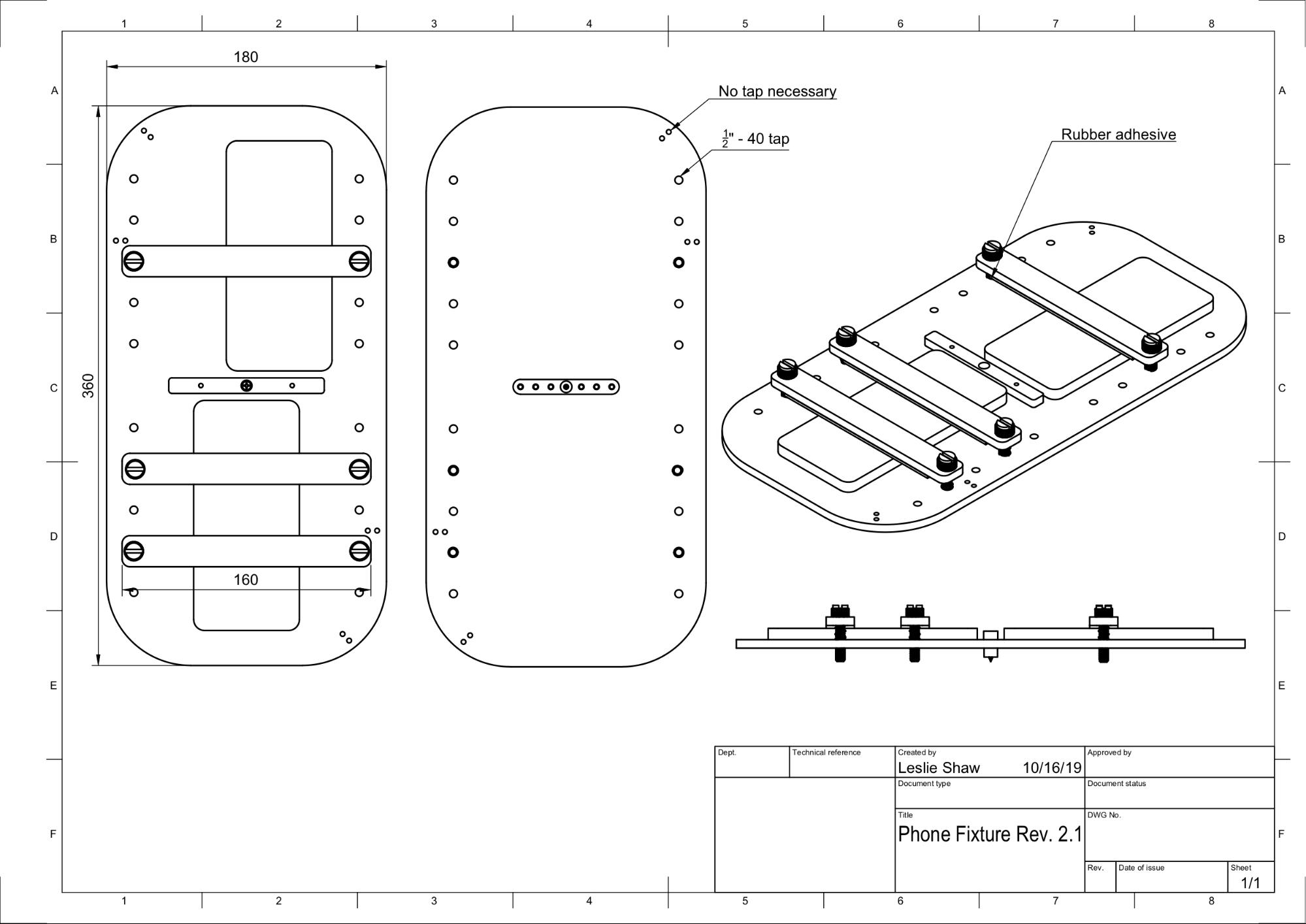
図 11. スマートフォン固定具の機械製図
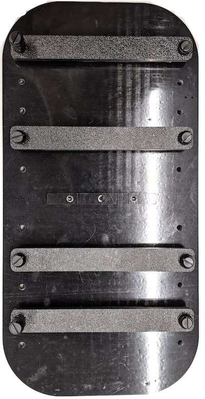
図 12. 組み立て済みのスマートフォン固定具
ステップ 4: 引き戸用レールを組み立てる
箱の上部と底部の引き戸用レールを前面に固定します。図 13 は、あらかじめ切っておいたねじ穴に差し込んだ 6-32 ねじを示しています。代わりに、タッピングねじを使用することもできます。
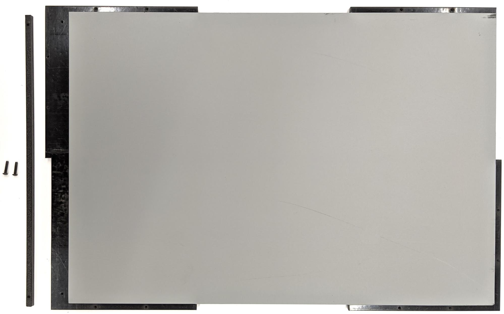
図 13. 箱の上部と底部に固定された引き戸用レール
ステップ 5: 照明を取り付ける
次のようにして、ライト ブラケットとディフューザーを取り付けます。
2 つのハンドル部品を重ねて、6-32 ねじで固定します(または、タッピングねじを使用します)。
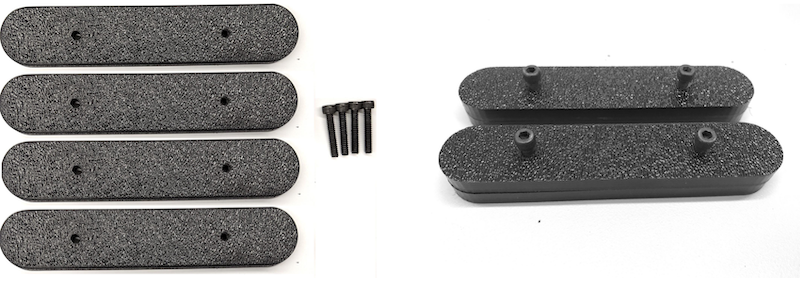
図 14. Sensor Fusion Box のハンドル部品と組み立て
4 組の 4-40 ねじ、ナット、袋ナットを用意して、照明キットに付属のマウント ブラケットを箱の壁面に固定します。
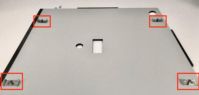
図 15. 箱の内壁の 4-40 ねじとライト ブラケット
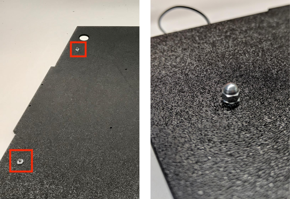
図 16. 箱の外面からねじに取り付けられたナットと袋ナット
ライト ストリップを巻くのに適切なサイズにライト ディフューザーを切断します(ライトにディフューザーが付属している場合には必要ありません)。

図 17. ライト ストリップとライト ディフューザー
ライト ディフューザーをストリップのまわりに巻いて、テープを使って背面で固定します。

図 18. 背面からテープで固定されたライト ストリップとライト ディフューザー
ライトをブラケットにはめ込みます(きつい場合があります)。

図 19. ブラケットに取り付けた後のライト
ステップ 6: スマートフォン固定具をサーボプレートに取り付ける
次のようにして、スマートフォン固定具をサーボプレートに取り付けます。
4 本の 6-32 ねじとサーボプレートを用意して、壁にサーボを固定します。
サーボを内壁に固定し、外壁のサーボプレートに内側からねじを差し込みます。
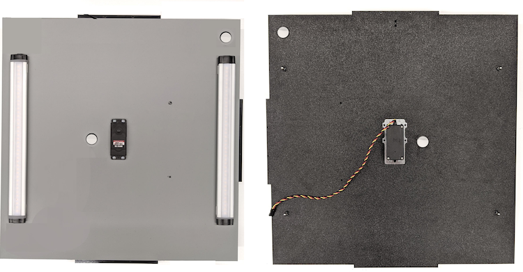
図 20. 6-32 ねじで固定したサーボとサーボプレート
ナイロックを使ってスマートフォン固定具をサーボに固定します。シャフトの中心をサーボの回転中心に押し込みます。
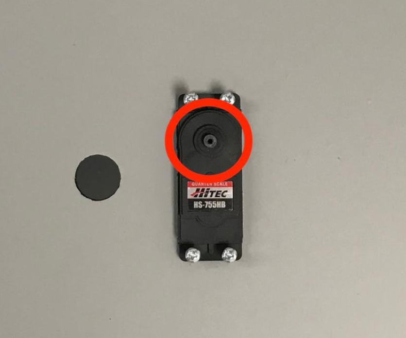
図 21. サーボギア
サーボに付属のサーボねじを使用し、サーボアームを貫通させてサーボギアにスマートフォン固定具をねじ止めします(1.2 N*m または 8.9 in*lbf)。
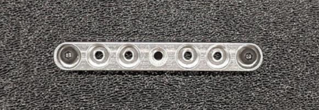
図 22. サーボアーム
ステップ 7: 最終組み立て
次のようにして、Sensor Fusion Box の組み立てを完了させます。
Android 13 以上では、センサー フュージョン テスト装置に Android 13 Arduino 照明コントローラが付属します(Android 12 以下では、センサー フュージョン装置が、6 チャンネル Arduino コントローラか、Canakit コントローラが付属した状態で出荷されます。Android 11 から Android 12 までを搭載したデバイスは、Android 13 コントローラ、6 チャンネル Arduino コントローラ、または Canakit コントローラに対応しています)。サーボ拡張機能をサーボ コントローラの任意のチャンネルに接続します。GND は黒いワイヤー、VCC は赤いワイヤー、SIG は黄色いワイヤーに対応しています。
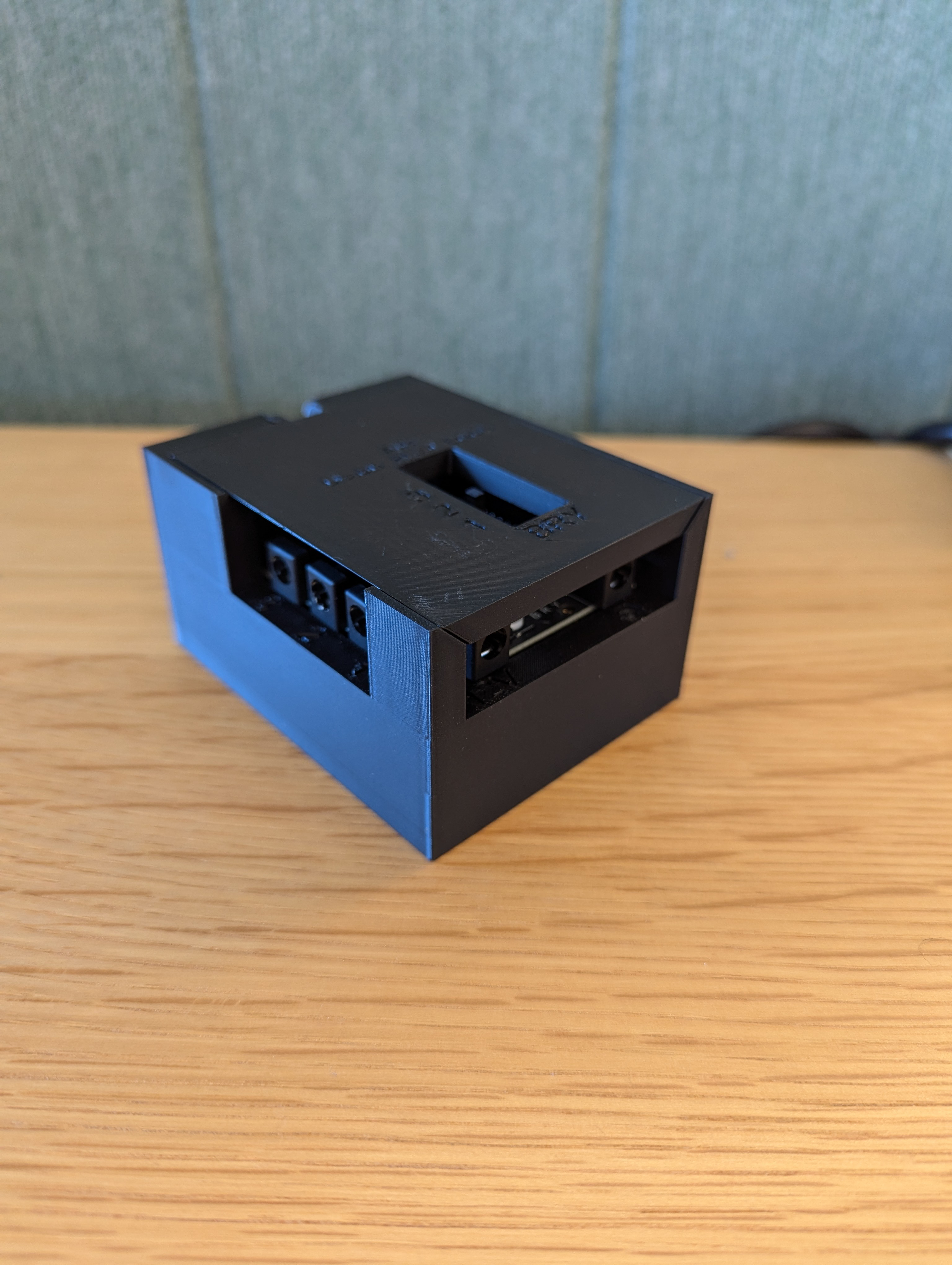
図 23. Arduino 照明コントローラ Rev3
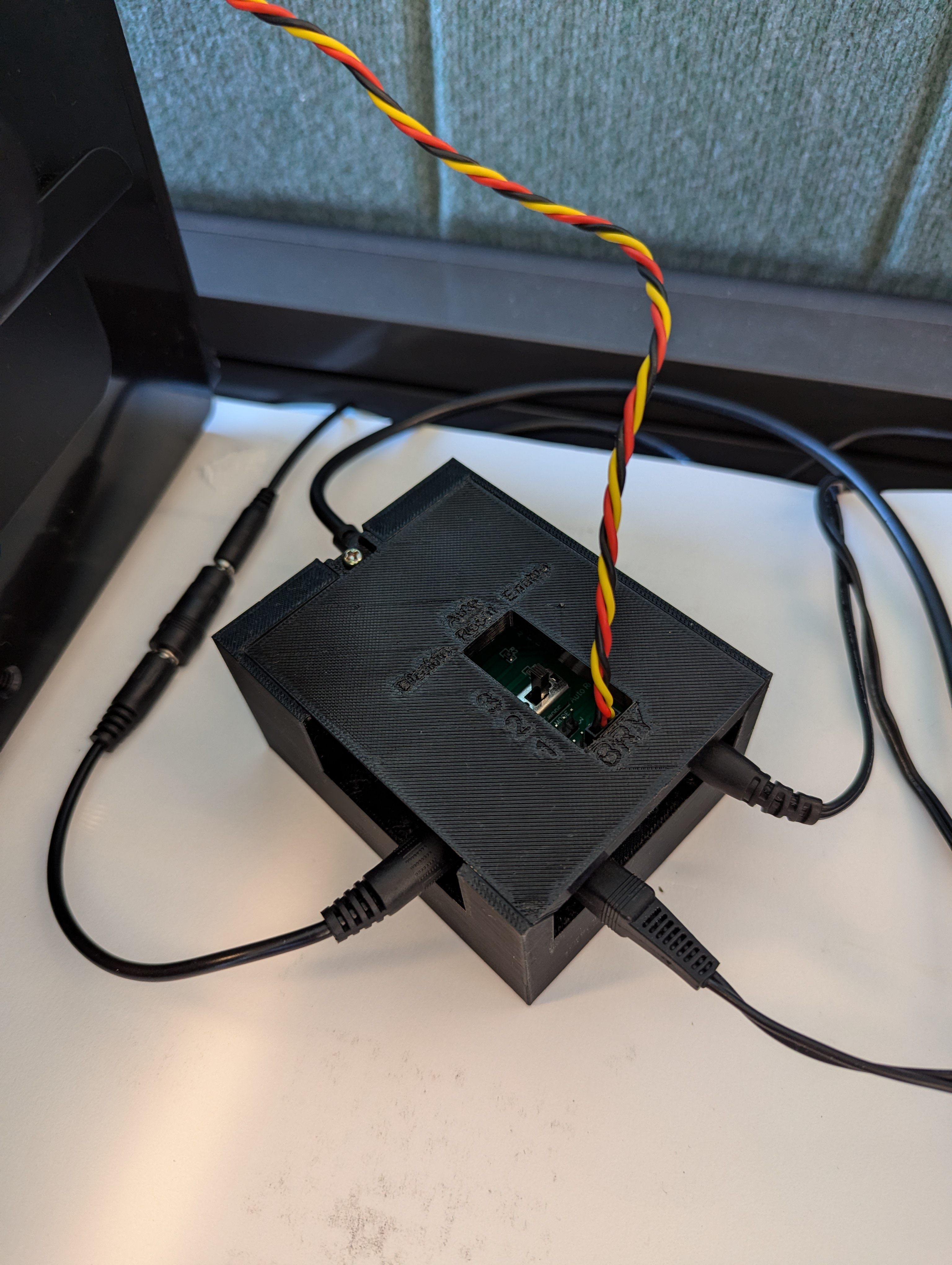
図 24. Arduino 照明コントローラ Rev3 の接続例
箱をテープで貼り合わせ、部品をねじで組み合わせます。一部の部品にはあらかじめ穴を開けておく必要があります。
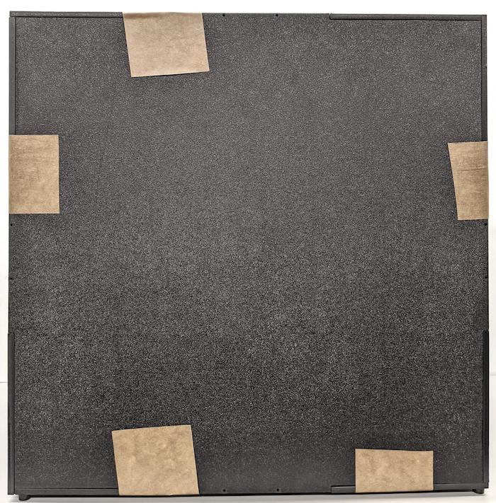
図 25. テープで固定されたセンサー フュージョン テスト装置
Android 15 以上の場合は、近所のプリント ショップで checkerboard.pdf ファイル(コードベースの test/sensor_fusion
ディレクトリにあります)を印刷してもらいます。用紙のサイズは 18 x 18 インチ、チェッカーボードのパターンを用紙の幅にします。そして、チャートをスマートフォン固定具の反対側の壁に貼ります。
望遠カメラなどの画角の狭いカメラの場合は、近所のプリント ショップで縦横比を保存した縮小版を作ってもらいます(たとえば、50% に縮小したチャートは 9 x 9 インチの用紙に印刷されます)。
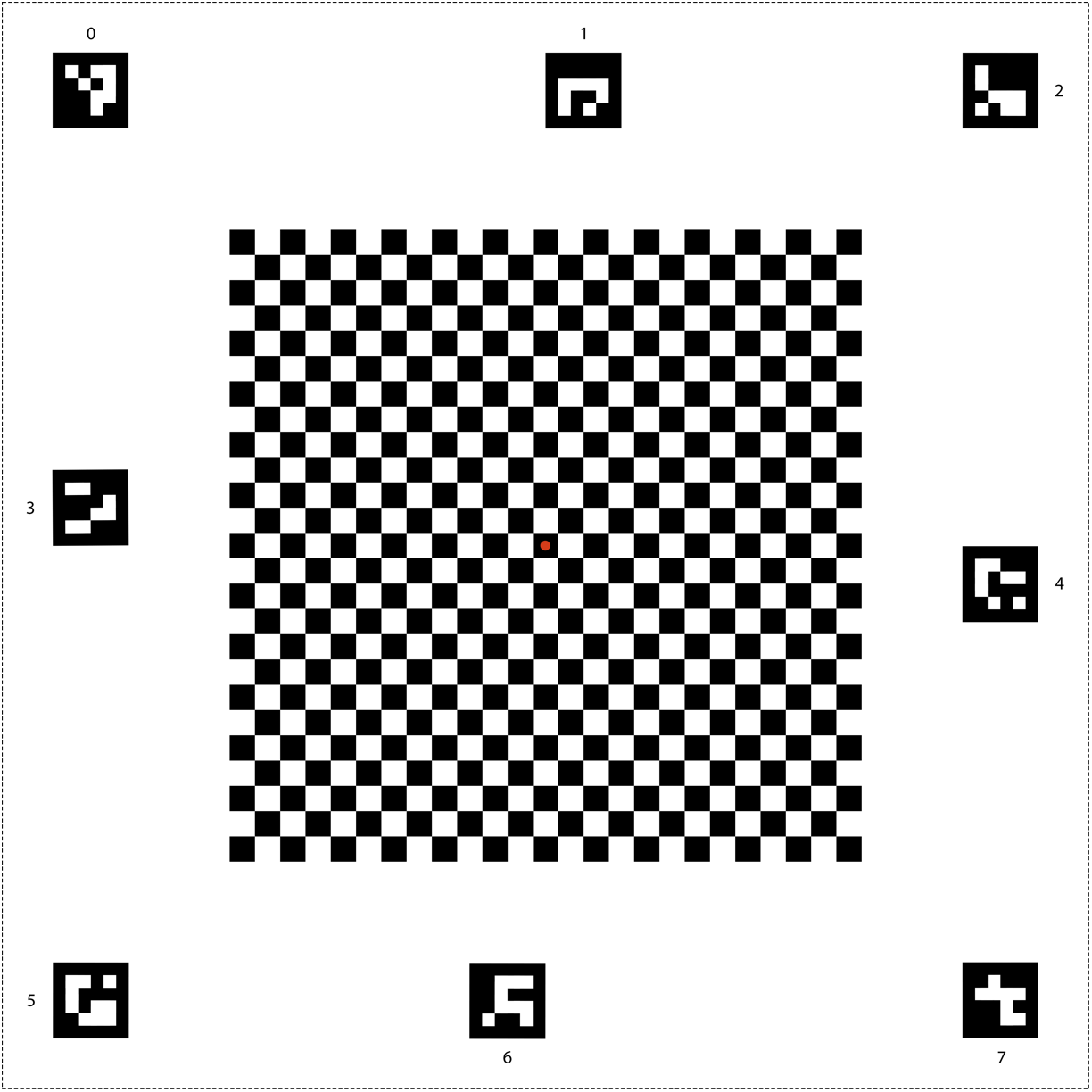
図 26. Android 15 以上用のチェッカーボード チャート
図 27 のように、固定具に置いたとき、チェッカーボードの中心にある赤い点が、カメラにまっすぐ向いていることを確認します。
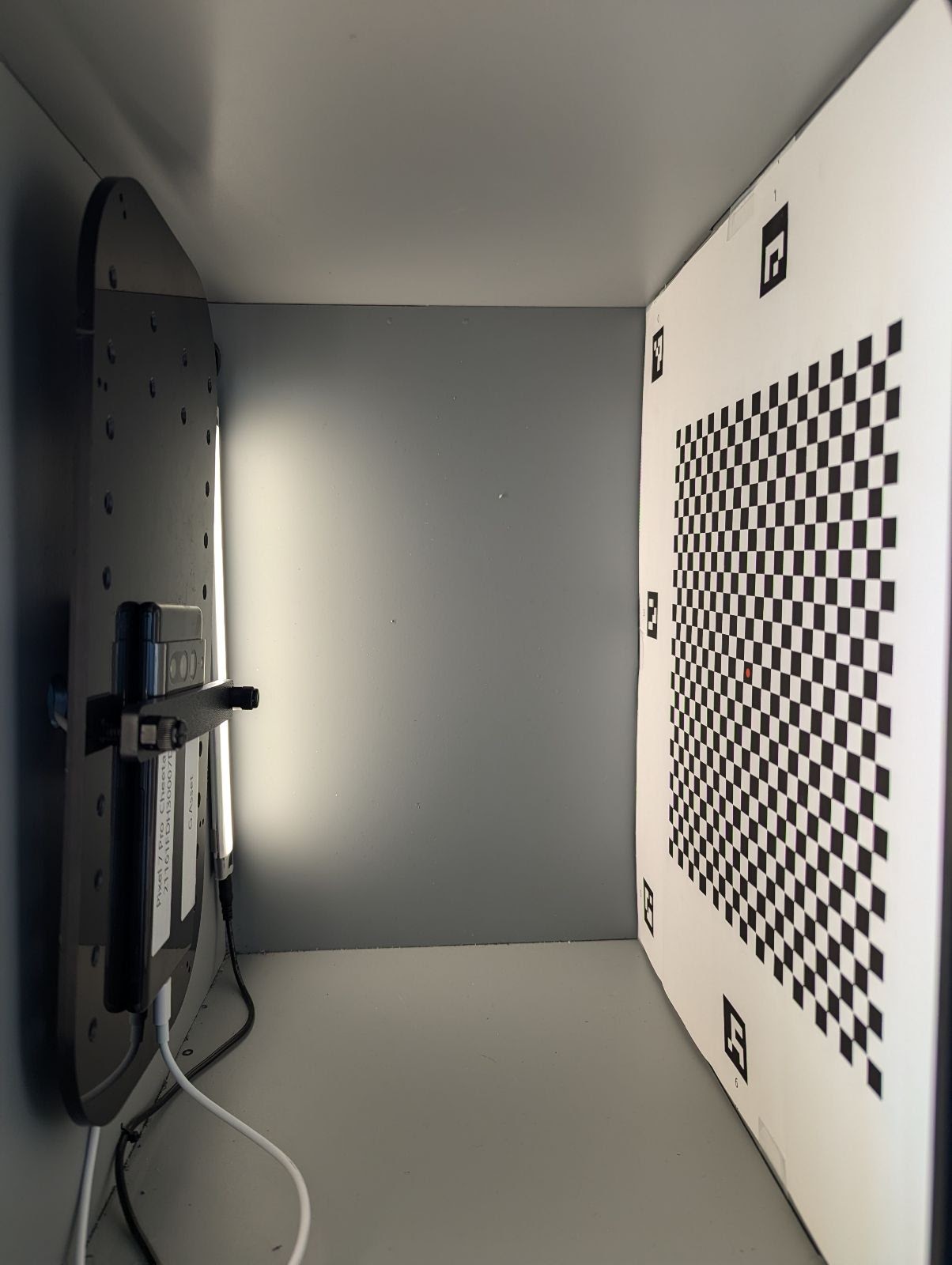
図 27. 印刷され、スマートフォン固定具の反対側の壁にテープで貼られたチェッカーボード
このページのコンテンツやコードサンプルは、コンテンツ ライセンスに記載のライセンスに従います。Java および OpenJDK は Oracle および関連会社の商標または登録商標です。
最終更新日 2025-05-08 UTC。
[[["わかりやすい","easyToUnderstand","thumb-up"],["問題の解決に役立った","solvedMyProblem","thumb-up"],["その他","otherUp","thumb-up"]],[["必要な情報がない","missingTheInformationINeed","thumb-down"],["複雑すぎる / 手順が多すぎる","tooComplicatedTooManySteps","thumb-down"],["最新ではない","outOfDate","thumb-down"],["翻訳に関する問題","translationIssue","thumb-down"],["サンプル / コードに問題がある","samplesCodeIssue","thumb-down"],["その他","otherDown","thumb-down"]],["最終更新日 2025-05-08 UTC。"],[],[],null,["# Obtain a sensor fusion box\n\nThis page provides information on how to purchase or assemble a Sensor Fusion\nBox. The Sensor Fusion Box is used in the CameraITS `sensor_fusion` test and\n`multi-camera` sync test. It provides a consistent test environment for\nmeasuring timestamp accuracy of sensors for Android\ndevices, specifically camera image sensors and gyroscopes. It consists of\nplastic box components that are laser cut from\ncomputer-aided design (CAD) drawings and a Servo Control Box.\n\nYou can purchase a Sensor Fusion Box or build your own.\n\nPurchase a Sensor Fusion Box\n----------------------------\n\nWe recommend purchasing a Sensor Fusion Box from one of the following qualified\nvendors.\n\n- *Byte Bridge Inc.* \n\n USA: 1502 Crocker Ave, Hayward, CA 94544-7037 \n\n China: 22F #06-08, Hongwell International Plaza Tower A,\n 1600 West Zhongshan Road, Xuhui, Shanghai, 200235 \n\n [www.bytebt.com](https://www.bytebt.com/) \n\n androidpartner@bytebt.com \n\n USA: +1-510-373-8899 \n\n China: +86-400-8866-490\n\n- *JFT CO LTD 捷富通科技有限公司 (previously known as MYWAY DESIGN)* \n\n China: No. 40, Lane 22, Heai Road, Wujing Town, Minhang District, Shanghai, China \n\n Taiwan: 4F., No. 163, Fu-Ying Road, XinZhuang District, New Taipei City 242, Taiwan \n\n [www.jftcoltd.com](https://www.jftcoltd.com) \n\n service@jfttec.com or its.sales@jfttec.com \n\n China:+86-021-64909136 \n\n Taiwan: 886-2-29089060\n\n| **Note:** For additional support for foldable and large form factor devices, you can purchase the [foldable kit](/docs/compatibility/cts/its-accessories-foldable-kit).\n\nBuild a Sensor Fusion Box\n-------------------------\n\nThis section includes step-by-step instructions for assembling a Sensor Fusion\nBox from laser-cut acrylonitrile butadiene styrene (ABS) components (shown in\nFigure 1).\n\n\u003cbr /\u003e\n\n\n**Figure 1.** Mechanical drawing of Sensor Fusion Box components\n\n### Required tools\n\nBefore starting, ensure you have downloaded the technical drawings for the\nSensor Fusion Box (included in the\n[Sensor Fusion Box zip file](/static/docs/compatibility/cts/sensor_fusion_1_8.zip))\nand have the following tools available:\n\n- Phillips head screwdriver\n- JIS head screwdriver\n- Hex keys\n- Power drill set\n- X-ACTO knife\n- Tape\n\n### Step 1: Apply vinyl stickers\n\nAfter creating the ABS components with a laser\ncutter, apply vinyl stickers to the plastic box to get the proper color control\non the interior of the test box:\n\n1. Apply vinyl on the smooth side of the ABS\n as shown in Figure 2. For helpful tips on applying vinyl, refer to\n [wikiHow](https://www.wikihow.com/Install-a-Vinyl-Graphic).\n\n2. Cut out the necessary holes on the vinyl with the exacto knife.\n\n \u003cbr /\u003e\n\n\n **Figure 2.** ABS pieces with vinyl applied on the smooth side (interior of\n the box)\n3. Using acrylic glue, glue the round ABS pieces onto the four corners of the\n bottom panel.\n\n \u003cbr /\u003e\n\n\n **Figure 3.** Bottom panel with round ABS pieces glued to the four corners.\n\n### Step 2: Prepare phone mount and attach servo mount\n\nTo prepare the phone mount to attach to the servo:\n\n1. Tap 20 holes on the phone fixture with a 1/4\"-20 drill bit.\n\n \u003cbr /\u003e\n\n\n **Figure 4.** Phone fixture with tapped holes\n2. Make sure you have the ABS cut outs, nylon thumb screws, nylon nuts\n (for adjusting screw height if necessary), the C1 spline\n actobotics dual servo arm, 4-40 screws, and compression springs.\n\n \u003cbr /\u003e\n\n\n **Figure 5.** Phone mount parts\n3. Apply the 4-40 screws and tighten (1.2 N\\*m or 8.9 in\\*lbf) the\n servo arm to the back of the phone mount. Using the same screws and\n 4-40 cap nuts, tighten the phone divider ABS cut out on the front side of\n the phone mount.\n\n \u003cbr /\u003e\n\n\n **Figure 6.** Shaft on the back of fixture, tightened by screws applied\n from the front\n\n \u003cbr /\u003e\n\n\n **Figure 7.** 4-40, 3/4\" long screws and 4-40 cap nuts\n\n \u003cbr /\u003e\n\n\n **Figure 8.** Back (left) and front (right) of the phone mount\n\n### Step 3: Attach phone clamps\n\nTo attach the phone clamps:\n\n1. Cut the neoprene sheet according to the shape of the ABS cut-out\n clamps, but leave one inch shorter from both ends as shown in Figure 9.\n After cutting the neoprene sheet accordingly, apply the pieces to the ABS\n cut-out clamps as in Figure 8.\n\n \u003cbr /\u003e\n\n\n **Figure 9.** ABS clamp with neoprene sheet applied\n2. Attach nylon thumb screws and spring wire to the clamp. Add nylon\n nuts to reduce screw length, as needed.\n\n \u003cbr /\u003e\n\n\n **Figure 10.** Clamp with neoprene sheet, thumb screws, nylon nuts, and\n spring wire\n3. Screw the phone clamps' thumb screws into the tapped holes of the phone\n fixture as shown in Figure 11. You can adjust the location of the phone\n mounts depending on the size of the phones.\n\n \u003cbr /\u003e\n\n\n **Figure 11.** Mechanical drawing of the phone fixture\n\n \u003cbr /\u003e\n\n\n **Figure 12.** Assembled phone fixture\n\n### Step 4: Assemble sliding door rail\n\n1. Fix sliding panel rails on the top and bottom of the box toward the front.\n Figure 13 shows 6-32 screws on pre-tapped holes. Alternatively, you can use\n self-tapping screws.\n\n \u003cbr /\u003e\n\n\n **Figure 13.** Fixed sliding panel rail on top and bottom of box\n\n### Step 5: Attach lighting\n\nTo attach the light brackets and diffuser:\n\n1. Stack two handle pieces on top of each other and assemble them using 6-32\n screws (or use self-tapping screws).\n\n \u003cbr /\u003e\n\n\n **Figure 14.** Sensor Fusion Box handle pieces and assembly\n2. Prepare four 4-40 screws, nuts, and acorn nuts to fix the mounting bracket\n from the lighting kit to the wall of the box.\n\n \u003cbr /\u003e\n\n\n **Figure 15.** 4-40 screws and light bracket on the interior wall of the box\n\n \u003cbr /\u003e\n\n\n **Figure 16.** Bolts and acorn bolts applied to the screws from the exterior\n of the box\n3. Cut the light diffuser to an appropriate size to wrap the light strips (not\n required if the lights come with the diffuser).\n\n \u003cbr /\u003e\n\n\n **Figure 17.** Light strips and light diffusers\n4. Wrap the light diffuser around the strip and tape it at the back.\n\n \u003cbr /\u003e\n\n\n **Figure 18.** Light strips and light diffusers taped from the back\n5. Snap the lights into the brackets (can be a tight fit).\n\n \u003cbr /\u003e\n\n\n **Figure 19.** Lights mounted in brackets\n\n### Step 6: Attach phone fixture to servo plate\n\nTo attach the phone fixture to the servo plate:\n\n1. Prepare four 6-32 screws and a servo plate to fix the servo onto the wall.\n Fix the servo onto the interior wall and insert the screws from the inside\n into the servo plate on the exterior wall.\n\n \u003cbr /\u003e\n\n\n **Figure 20.** Servo and servo plate held in place with 6-32 screws\n2. Secure the phone fixture onto the servo with nylocks (pushing the center of the\n shaft into the servo's rotation center).\n\n **Figure 21.** Servo gear\n3. Using the servo screw that came with the servo, screw (1.2 N\\*m or\n 8.9 in\\*lbf) the phone fixture onto the servo gear through the servo\n arm.\n\n **Figure 22.** Servo arm\n\n### Step 7: Final assembly\n\nTo complete assembly of the Sensor Fusion Box:\n\n1. From Android 13, the sensor fusion test rig comes\n with the\n [Android 13 Arduino lighting controller](/docs/compatibility/cts/sensor-fusion-controller).\n (In Android 12\n or lower, the sensor fusion rig shipped with a 6-channel Arduino\n controller or a Canakit controller. Devices running\n Android 11 to Android 12\n are compatible with the Android 13 controller, 6-channel Arduino controller,\n or Canakit controller.) Connect the servo extension to any channel of the\n servo controller, where GND corresponds to black wire, VCC corresponds to\n the red wire, and SIG corresponds to the yellow wire.\n\n \u003cbr /\u003e\n\n\n **Figure 23.** Arduino Lighting Controller Rev3\n\n \u003cbr /\u003e\n\n\n **Figure 24.** Arduino lighting controller Rev3 connection sample\n2. Tape the box together, then screw the parts together (you might need to\n pre-drill holes in some parts).\n\n **Figure 25.** Taped sensor fusion test rig\n3. For Android 15 or higher, work with your local print\n shop to print out the checkerboard.pdf file (included in the\n `test/sensor_fusion` directory of the codebase)\n on 18 x 18 inch paper with the checkerboard pattern the width of the paper,\n and tape the chart on the wall opposite the phone fixture.\n\n For cameras with smaller fields of view, such as telephoto cameras, work\n with your local print shop to create proportionally scaled versions of the\n checkerboard. (For example, a 50% scaled chart would be printed on 9 x 9\n inch paper.)\n\n **Figure 26.** Checkerboard chart for Android 15 or\n higher.\n\n Make sure the red dot in the center of the checkerboard is directly facing\n the camera when placed on the fixture, as shown in Figure 27.\n\n **Figure 27.** Checkerboard printed and taped to the opposite wall of phone\n fixture."]]