
Halaman ini memberikan informasi tentang cara membeli atau merakit Sensor Fusion Box. Sensor Fusion Box digunakan dalam pengujian sensor_fusion CameraITS dan pengujian sinkronisasi multi-camera. Sensor Fusion Box menyediakan lingkungan pengujian yang konsisten untuk mengukur akurasi stempel waktu sensor untuk perangkat Android, khususnya sensor gambar kamera dan giroskop. Sensor Fusion Box terdiri dari komponen kotak plastik yang dipotong laser dari gambar desain berbantuan komputer (CAD) dan Kotak Kontrol Servo.
Anda dapat membeli Sensor Fusion Box atau membuat sendiri.
Membeli Sensor Fusion Box
Sebaiknya beli Sensor Fusion Box dari salah satu vendor yang memenuhi syarat berikut.
Byte Bridge Inc.
USA: 1502 Crocker Ave, Hayward, CA 94544-7037
China: 22F #06-08, Hongwell International Plaza Tower A, 1600 West Zhongshan Road, Xuhui, Shanghai, 200235
www.bytebt.com
androidpartner@bytebt.com
USA: +1-510-373-8899
China: +86-400-8866-490JFT CO LTD 捷富通科技有限公司 (previously known as MYWAY DESIGN)
China: No. 40, Lane 22, Heai Road, Wujing Town, Minhang District, Shanghai, China
Taiwan: 4F., No. 163, Fu-Ying Road, XinZhuang District, New Taipei City 242, Taiwan
www.jftcoltd.com
service@jfttec.com or its.sales@jfttec.com
China:+86-021-64909136
Taiwan: 886-2-29089060
Membuat Sensor Fusion Box
Bagian ini mencakup petunjuk langkah demi langkah untuk merakit Sensor Fusion Box dari komponen akrilonitril butadiena stirena (ABS) yang dipotong laser (ditampilkan di Gambar 1).
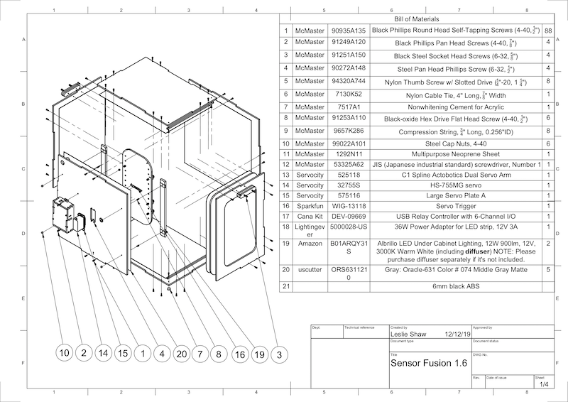
Gambar 1. Gambar mekanis komponen Sensor Fusion Box
Alat yang diperlukan
Sebelum memulai, pastikan Anda telah mendownload gambar teknis untuk Sensor Fusion Box (termasuk dalam file zip Sensor Fusion Box) dan memiliki alat berikut:
- Obeng head Phillips
- Obeng head JIS
- Kunci L
- Set bor listrik
- Pisau X-ACTO
- Pita
Langkah 1: Tempelkan stiker vinil
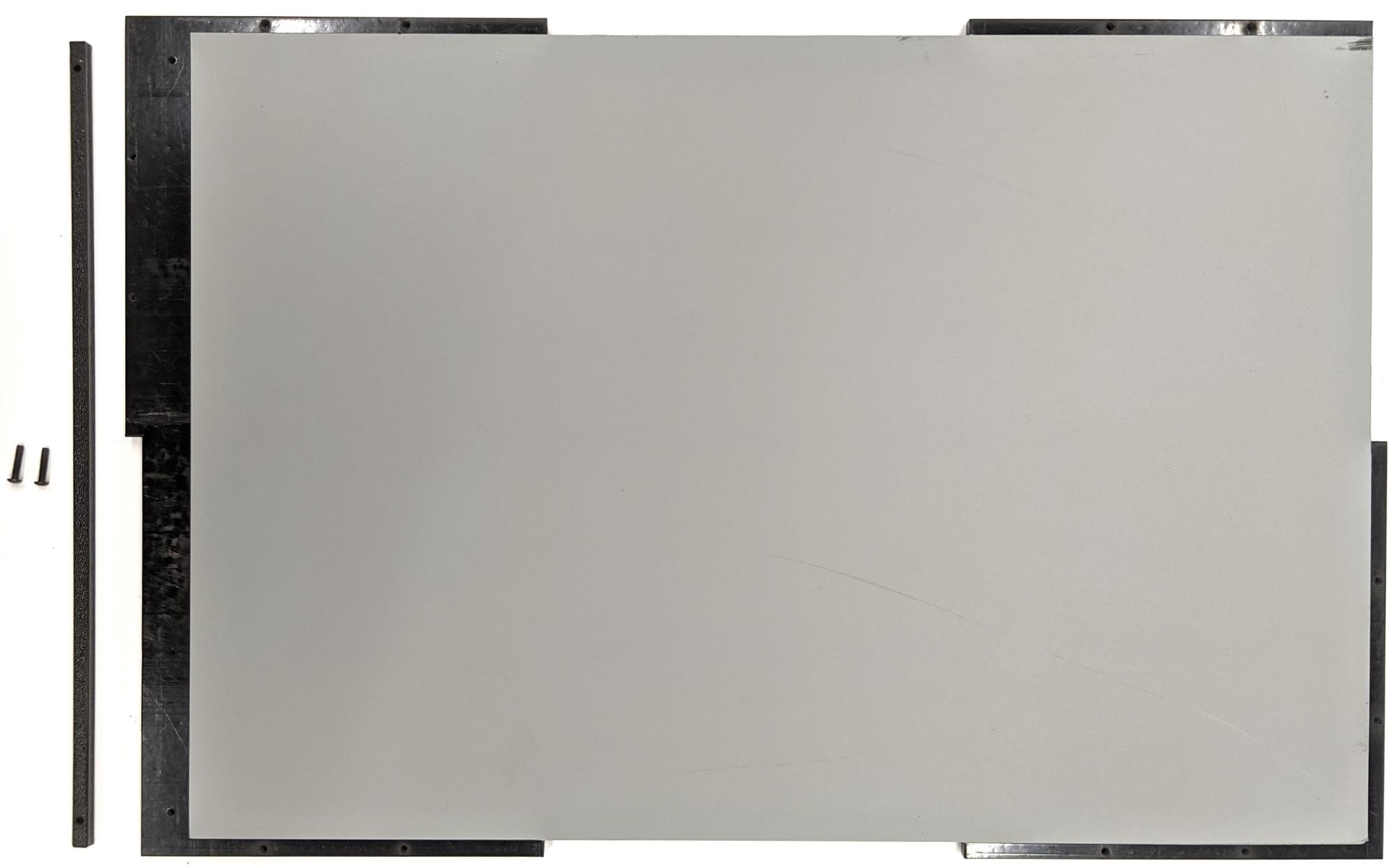
Setelah membuat komponen ABS dengan pemotong laser, tempelkan stiker vinil ke kotak plastik untuk mendapatkan kontrol warna yang tepat di bagian dalam kotak pengujian:
Tempelkan vinil di sisi halus ABS seperti yang ditunjukkan pada Gambar 2. Untuk mendapatkan tips bermanfaat tentang cara menempelkan vinil, lihat wikiHow.
Potong lubang yang diperlukan pada vinil dengan pisau exacto.
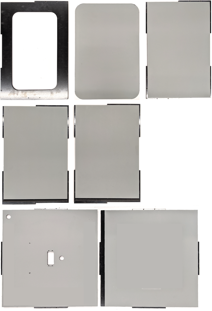
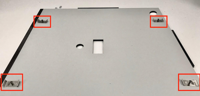
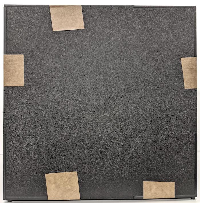
Gambar 2. Potongan ABS dengan vinil yang ditempelkan di sisi halus (bagian dalam kotak)Dengan menggunakan lem akrilik, rekatkan potongan ABS bulat ke empat sudut panel bawah.
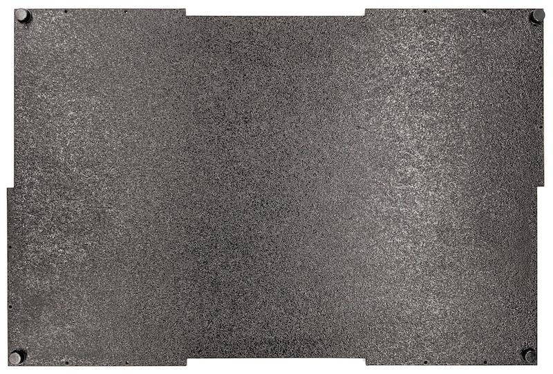
Gambar 3. Panel bawah dengan potongan ABS bulat yang direkatkan ke empat sudut.
Langkah 2: Siapkan dudukan ponsel dan pasang dudukan servo
Untuk menyiapkan dudukan ponsel agar dapat dipasang ke servo:
Buat 20 lubang pada dudukan ponsel dengan mata bor 1/4"-20.
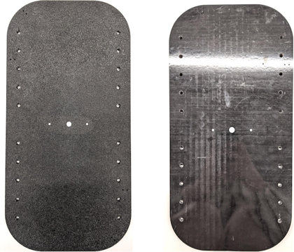
Gambar 4. Dudukan ponsel dengan lubang yang dibuatPastikan Anda memiliki potongan ABS, sekrup ibu jari nilon, mur nilon (untuk menyesuaikan tinggi sekrup jika diperlukan), lengan servo ganda actobotics spline C1, sekrup 4-40, dan pegas kompresi.
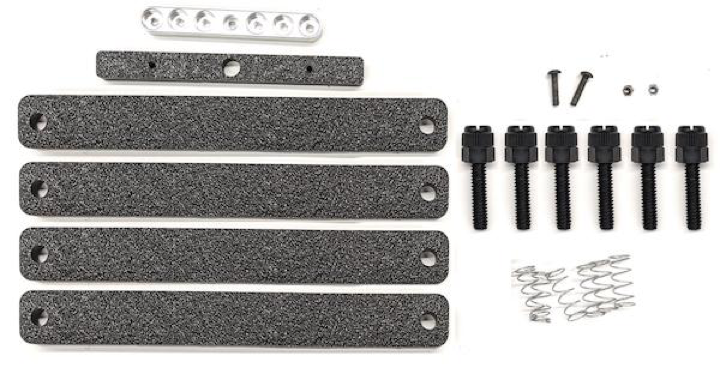
Gambar 5. Komponen dudukan ponselPasang sekrup 4-40 dan kencangkan (1,2 N*m atau 8,9 in*lbf) lengan servo ke bagian belakang dudukan ponsel. Dengan menggunakan sekrup yang sama dan mur tutup 4-40, kencangkan potongan ABS pembagi ponsel di sisi depan dudukan ponsel.
Gambar 6. Poros di bagian belakang dudukan, dikencangkan dengan sekrup yang dipasang dari depan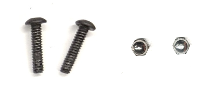
Gambar 7. Sekrup 4-40, panjang 3/4" dan mur tutup 4-40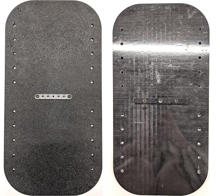
Gambar 8. Bagian belakang (kiri) dan depan (kanan) dudukan ponsel
Langkah 3: Pasang penjepit ponsel
Untuk memasang penjepit ponsel:
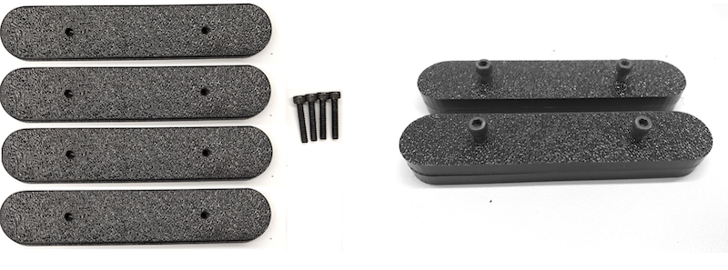
Potong lembaran neoprene sesuai dengan bentuk penjepit potongan ABS, tetapi sisakan satu inci lebih pendek dari kedua ujungnya seperti yang ditunjukkan pada Gambar 9. Setelah memotong lembaran neoprene sesuai dengan bentuknya, tempelkan potongan tersebut ke penjepit potongan ABS seperti pada Gambar 8.
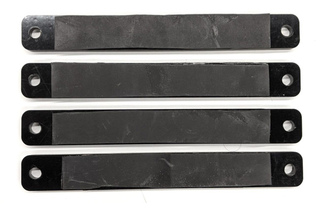
Gambar 9. Penjepit ABS dengan lembaran neoprene yang ditempelkanPasang sekrup ibu jari nilon dan kawat pegas ke penjepit. Tambahkan mur nilon untuk mengurangi panjang sekrup, jika diperlukan.
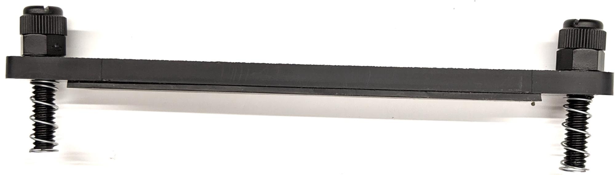
Gambar 10. Penjepit dengan lembaran neoprene, sekrup ibu jari, mur nilon, dan kawat pegasPasang sekrup ibu jari penjepit ponsel ke lubang yang dibuat pada dudukan ponsel seperti yang ditunjukkan pada Gambar 11. Anda dapat menyesuaikan lokasi dudukan ponsel bergantung pada ukuran ponsel.
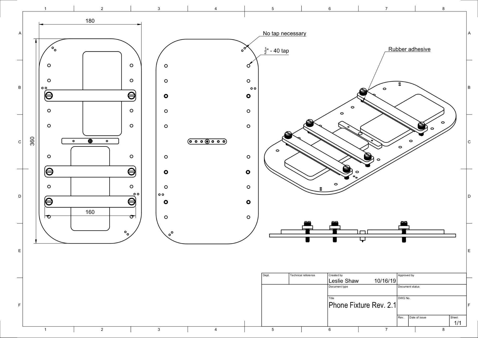
Gambar 11. Gambar mekanis dudukan ponsel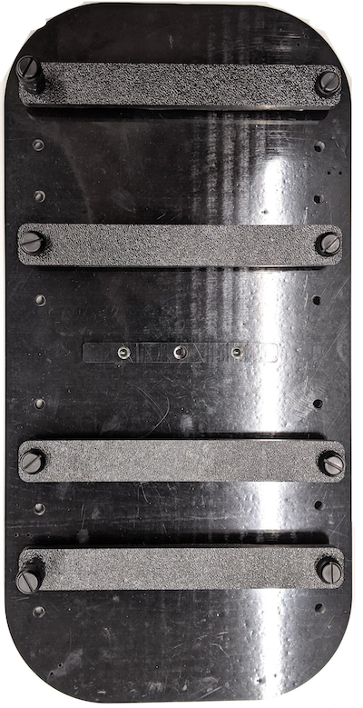
Gambar 12. Dudukan ponsel yang dirakit
Langkah 4: Rakit rel pintu geser
Pasang rel panel geser di bagian atas dan bawah kotak ke arah depan. Gambar 13 menunjukkan sekrup 6-32 pada lubang yang dibuat. Atau, Anda dapat menggunakan sekrup self-tapping.
Gambar 13. Rel panel geser tetap di bagian atas dan bawah kotak
Langkah 5: Pasang pencahayaan
Untuk memasang braket lampu dan diffuser:
Tumpuk dua bagian pegangan di atas satu sama lain dan rakit menggunakan sekrup 6-32 (atau gunakan sekrup self-tapping).
Gambar 14. Komponen pegangan dan rakitan Sensor Fusion BoxSiapkan empat sekrup 4-40, mur, dan mur acorn untuk memasang braket pemasangan dari kit pencahayaan ke dinding kotak.
Gambar 15. Sekrup 4-40 dan braket lampu di dinding bagian dalam kotak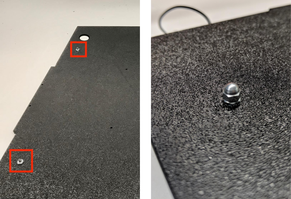
Gambar 16. Baut dan baut acorn yang dipasang ke sekrup dari bagian luar kotakPotong diffuser lampu ke ukuran yang sesuai untuk membungkus strip lampu (tidak diperlukan jika lampu dilengkapi dengan diffuser).
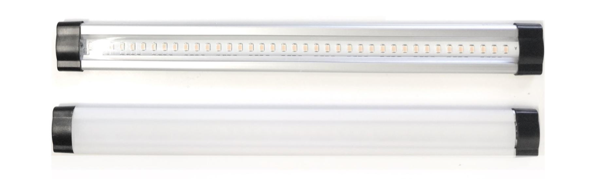
Gambar 17. Strip lampu dan diffuser lampuBungkus diffuser lampu di sekitar strip dan rekatkan di bagian belakang.
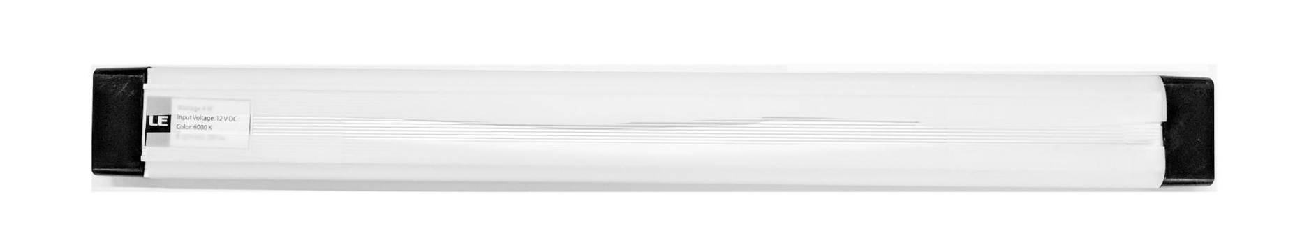
Gambar 18. Strip lampu dan diffuser lampu yang direkatkan dari belakangPasang lampu ke dalam braket (mungkin akan pas).
Gambar 19. Lampu yang dipasang di braket
Langkah 6: Pasang dudukan ponsel ke pelat servo
Untuk memasang dudukan ponsel ke pelat servo:
Siapkan empat sekrup 6-32 dan pelat servo untuk memasang servo ke dinding. Pasang servo ke dinding bagian dalam dan masukkan sekrup dari dalam ke pelat servo di dinding bagian luar.
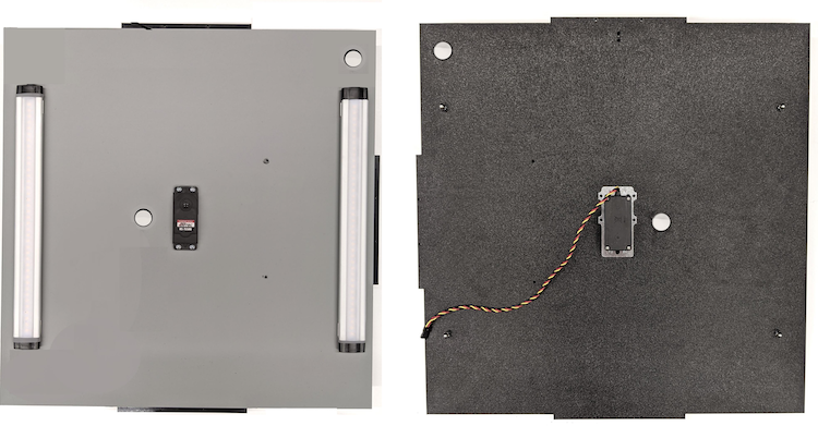
Gambar 20. Servo dan pelat servo yang dipasang dengan sekrup 6-32Amankan dudukan ponsel ke servo dengan nylock (dorong bagian tengah poros ke pusat rotasi servo).
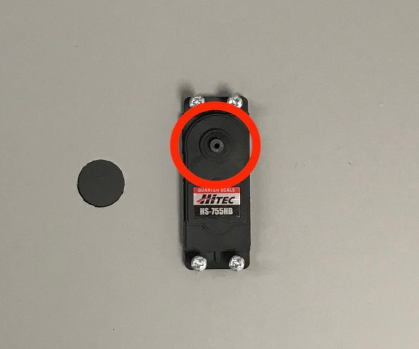
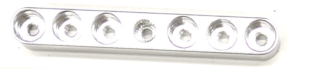
Gambar 21. Roda gigi servo
Dengan menggunakan sekrup servo yang disertakan bersama servo, pasang (1,2 N*m atau 8,9 in*lbf) dudukan ponsel ke roda gigi servo melalui lengan servo.
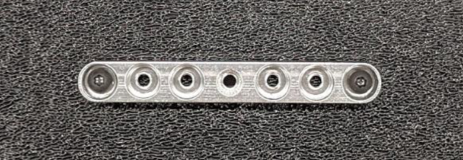
Gambar 22. Lengan servo
Langkah 7: Perakitan akhir
Untuk menyelesaikan perakitan Sensor Fusion Box:
Mulai Android 13, rig pengujian sensor fusion dilengkapi dengan pengontrol pencahayaan Arduino Android 13. (Di Android 12 atau yang lebih rendah, rig sensor fusion dikirimkan dengan pengontrol Arduino 6 saluran atau pengontrol Canakit. Perangkat yang menjalankan Android 11 hingga Android 12 kompatibel dengan pengontrol Android 13, pengontrol Arduino 6 saluran, atau pengontrol Canakit.) Hubungkan ekstensi servo ke saluran pengontrol servo mana pun, dengan GND sesuai dengan kabel hitam, VCC sesuai dengan kabel merah, dan SIG sesuai dengan kabel kuning.
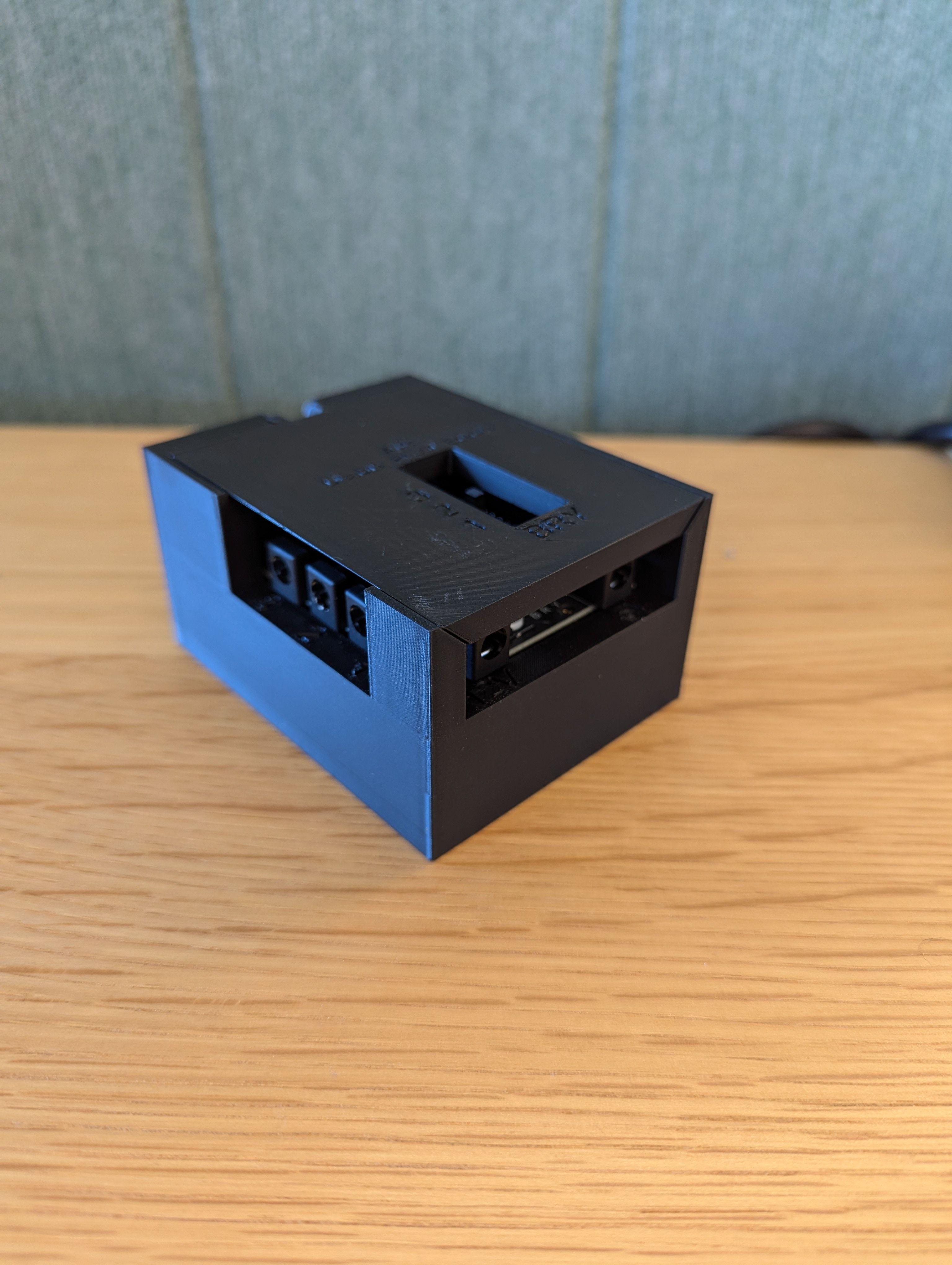
Gambar 23. Pengontrol Pencahayaan Arduino Rev3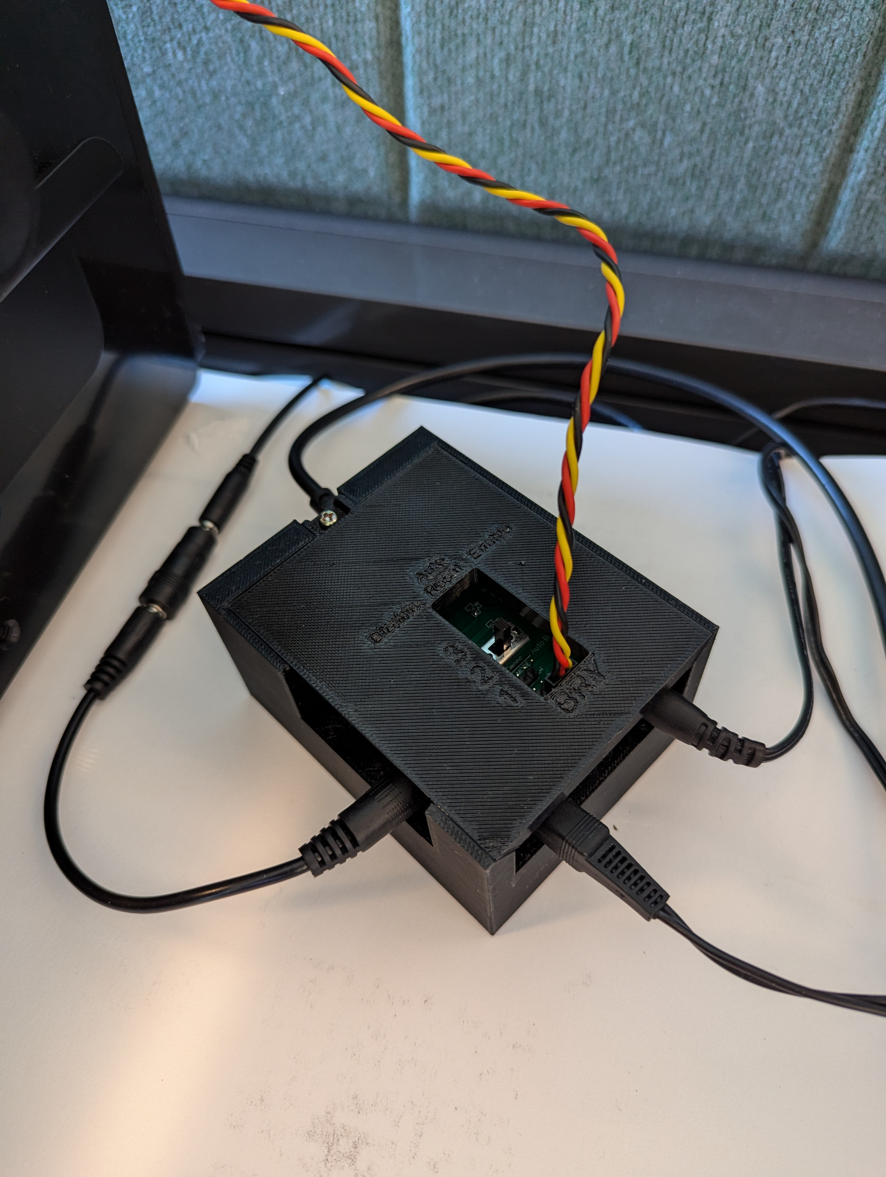
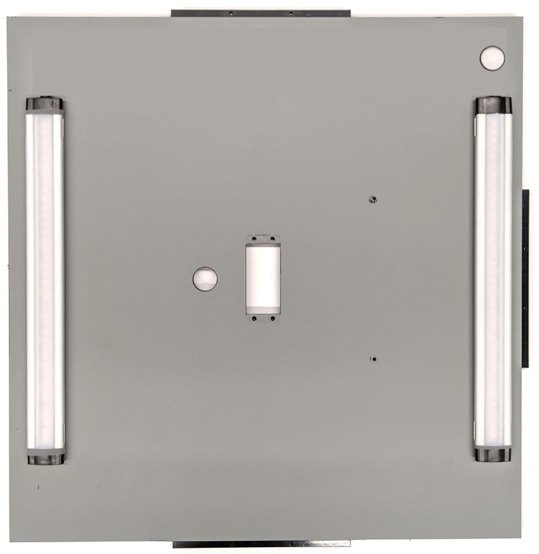
Gambar 24. Contoh koneksi pengontrol pencahayaan Arduino Rev3Rekatkan kotak, lalu pasang komponen dengan sekrup (Anda mungkin perlu membuat lubang bor awal di beberapa komponen).
Gambar 25. Rig pengujian sensor fusion yang direkatkan
Untuk Android 15 atau yang lebih tinggi, hubungi percetakan lokal untuk mencetak file checkerboard.pdf (termasuk dalam direktori
test/sensor_fusioncodebase) pada kertas berukuran 18 x 18 inci dengan pola papan catur selebar kertas, dan rekatkan diagram di dinding yang berlawanan dengan dudukan ponsel.Untuk kamera dengan ruang pandang yang lebih kecil, seperti kamera telefoto, hubungi percetakan lokal untuk membuat versi papan catur yang skalanya proporsional. (Misalnya, diagram dengan skala 50% akan dicetak pada kertas berukuran 9 x 9 inci.)
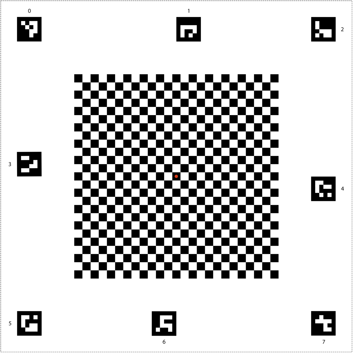
Gambar 26. Diagram papan catur untuk Android 15 atau yang lebih tinggi.
Pastikan titik merah di tengah papan catur menghadap langsung ke kamera saat ditempatkan di dudukan, seperti yang ditunjukkan pada Gambar 27.
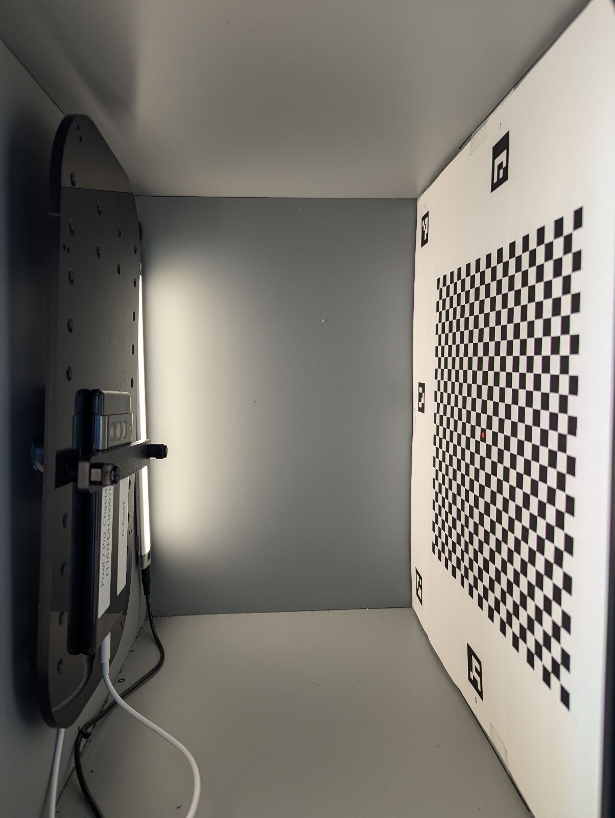
Gambar 27. Papan catur dicetak dan direkatkan ke dinding yang berlawanan dengan dudukan ponsel.