از 27 مارس 2025، توصیه می کنیم از android-latest-release به جای aosp-main برای ساختن و کمک به AOSP استفاده کنید. برای اطلاعات بیشتر، به تغییرات AOSP مراجعه کنید.
با مجموعهها، منظم بمانید
ذخیره و طبقهبندی محتوا براساس اولویتهای شما.
این صفحه اطلاعاتی در مورد نحوه خرید یا مونتاژ سنسور فیوژن باکس ارائه می دهد. Sensor Fusion Box در تست CameraITS sensor_fusion و تست همگام سازی multi-camera استفاده می شود. این یک محیط آزمایشی ثابت برای اندازهگیری دقت مهر زمانی سنسورها برای دستگاههای Android، بهویژه سنسورهای تصویر دوربین و ژیروسکوپها را فراهم میکند. این شامل اجزای جعبه پلاستیکی است که با لیزر از نقشه های طراحی به کمک کامپیوتر (CAD) برش داده شده اند و یک جعبه کنترل سروو.
شما می توانید یک جعبه سنسور فیوژن بخرید یا خودتان بسازید.
یک جعبه فیوژن سنسور بخرید
ما توصیه می کنیم جعبه سنسور فیوژن را از یکی از فروشندگان واجد شرایط زیر خریداری کنید.
Byte Bridge Inc. ایالات متحده آمریکا: 1502 Crocker Ave, Hayward, CA 94544-7037 چین: 22F #06-08، Hongwell International Plaza Tower A, 1600 West Zhongshan Road, Xuhui, Shanghai, 200235 www.bytebt.com androidpartner@bytebt.com ایالات متحده آمریکا: +1-510-373-8899 چین: +86-400-8866-490
JFT CO LTD 捷富通科技有限公司 (قبلاً با نام MYWAY DESIGN شناخته می شد) چین: پلاک 40، لین 22، جاده هیی، شهر ووجینگ، منطقه مینهنگ، شانگهای، چین تایوان: 4F.، شماره 163، جاده فو-یینگ، منطقه XinZhuang، شهر جدید تایپه 242، تایوان www.jftcoltd.com service@jfttec.com یا its.sales@jfttec.com چین: +86-021-64909136 تایوان: 886-2-29089060
یک جعبه فیوژن سنسور بسازید
این بخش شامل دستورالعمل های گام به گام برای مونتاژ جعبه فیوژن سنسور از اجزای اکریلونیتریل بوتادین استایرن (ABS) برش لیزری است (نشان داده شده در شکل 1).
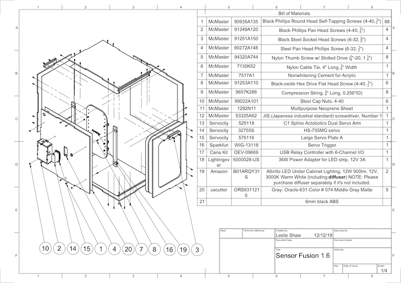
شکل 1. ترسیم مکانیکی اجزای جعبه فیوژن سنسور
ابزار مورد نیاز
قبل از شروع، مطمئن شوید که نقشه های فنی جعبه فیوژن سنسور (که در فایل فشرده Sensor Fusion Box موجود است) را دانلود کرده اید و ابزارهای زیر را در دسترس دارید:
پیچ گوشتی سر فیلیپس
پیچ گوشتی سر JIS
کلیدهای شش گوش
مجموعه مته برقی
چاقوی X-ACTO
نوار
مرحله 1: استیکرهای وینیل را اعمال کنید
پس از ایجاد اجزای ABS با کاتر لیزری، برچسب های وینیل را روی جعبه پلاستیکی بمالید تا کنترل رنگ مناسب را در داخل جعبه آزمایش به دست آورید:
همانطور که در شکل 2 نشان داده شده است، وینیل را در سمت صاف ABS اعمال کنید. برای راهنمایی های مفید در مورد استفاده از وینیل، به wikiHow مراجعه کنید.
سوراخ های لازم را روی وینیل با چاقوی اگزاکتو برش دهید.
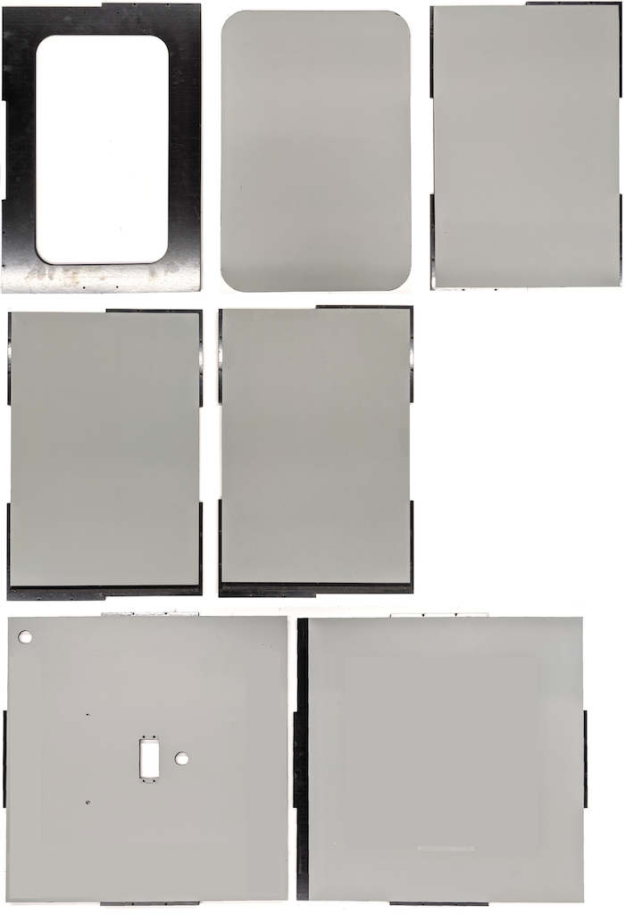
شکل 2. قطعات ABS با وینیل اعمال شده در سمت صاف (داخلی جعبه)
با استفاده از چسب اکریلیک، قطعات گرد ABS را روی چهار گوشه پانل زیرین بچسبانید.
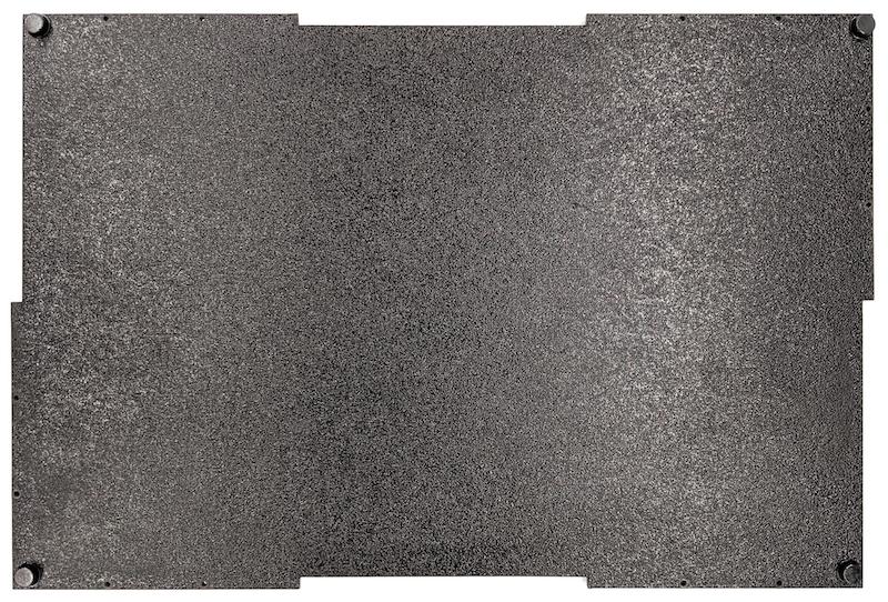
شکل 3. پانل پایین با قطعات گرد ABS که به چهار گوشه چسبانده شده است.
مرحله 2: پایه تلفن را آماده کرده و پایه سروو را وصل کنید
برای آماده کردن پایه تلفن برای اتصال به سروو:
با یک مته 1/4 اینچ تا 20 روی 20 سوراخ روی دستگاه تلفن ضربه بزنید.
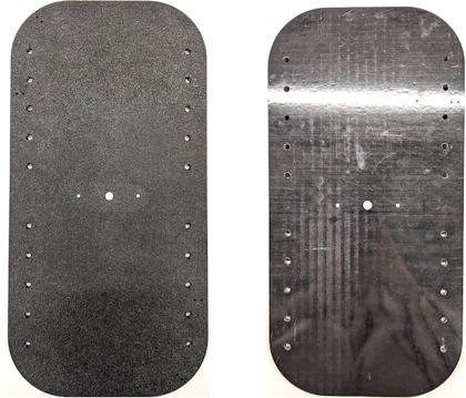
شکل 4. دستگاه تلفن با سوراخ های ضربه خورده
مطمئن شوید که برشهای ABS، پیچهای نایلونی انگشتی، مهرههای نایلونی (برای تنظیم ارتفاع پیچ در صورت لزوم)، بازوی سروو دوگانه Actobotics C1 spline، پیچهای 4-40 و فنرهای فشاری را دارید.
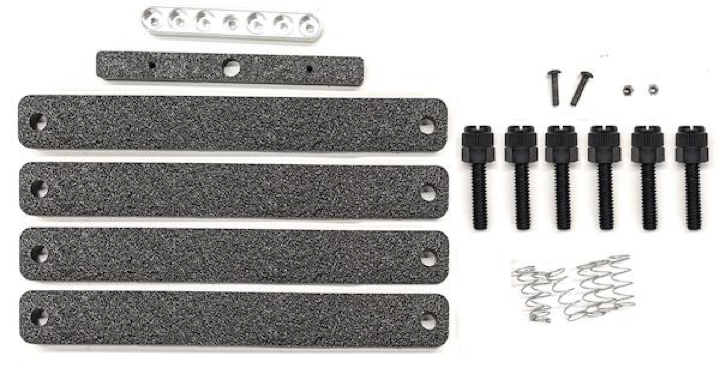
شکل 5. قطعات پایه تلفن
پیچ های 4-40 را ببندید و (1.2 N*m یا 8.9 اینچ*lbf) بازوی سروو را در پشت پایه تلفن محکم کنید. با استفاده از همان پیچها و مهرههای 4-40 کلاهکی، جداکننده ABS گوشی را که در قسمت جلوی پایه گوشی قرار دارد، محکم کنید.
شکل 6. شفت در پشت فیکسچر، با پیچ هایی که از جلو اعمال می شود سفت می شود
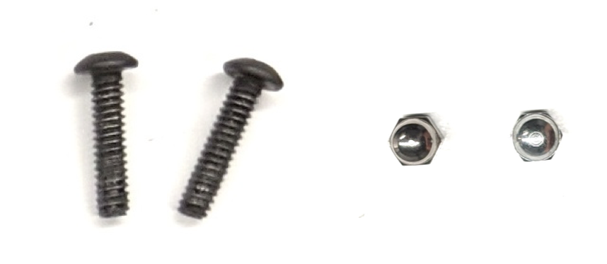
شکل 7. پیچ های بلند 4-40، 3/4 اینچی و مهره های درپوش 4-40
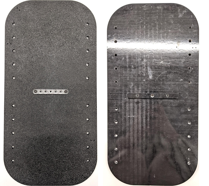
شکل 8. پشت (چپ) و جلو (راست) پایه تلفن
مرحله 3: گیره های تلفن را وصل کنید
برای اتصال گیره های گوشی:
ورق نئوپرن را مطابق شکل گیره های برش ABS برش دهید، اما همانطور که در شکل 9 نشان داده شده است، یک اینچ از دو انتها کوتاهتر بگذارید.
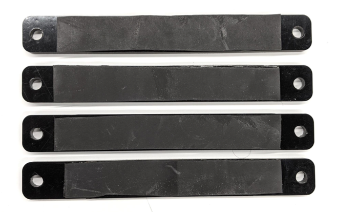
شکل 9. گیره ABS با ورق نئوپرن اعمال شده
پیچ های نایلونی و سیم فنر را به گیره وصل کنید. در صورت نیاز، مهره های نایلونی را برای کاهش طول پیچ اضافه کنید.
شکل 10. گیره با ورق نئوپرن، پیچ های انگشتی، مهره های نایلونی و سیم فنر
همانطور که در شکل 11 نشان داده شده است، پیچ های شست گیره های تلفن را در سوراخ های ضربه خورده دستگاه تلفن پیچ کنید. می توانید مکان پایه های تلفن را بسته به اندازه تلفن ها تنظیم کنید.
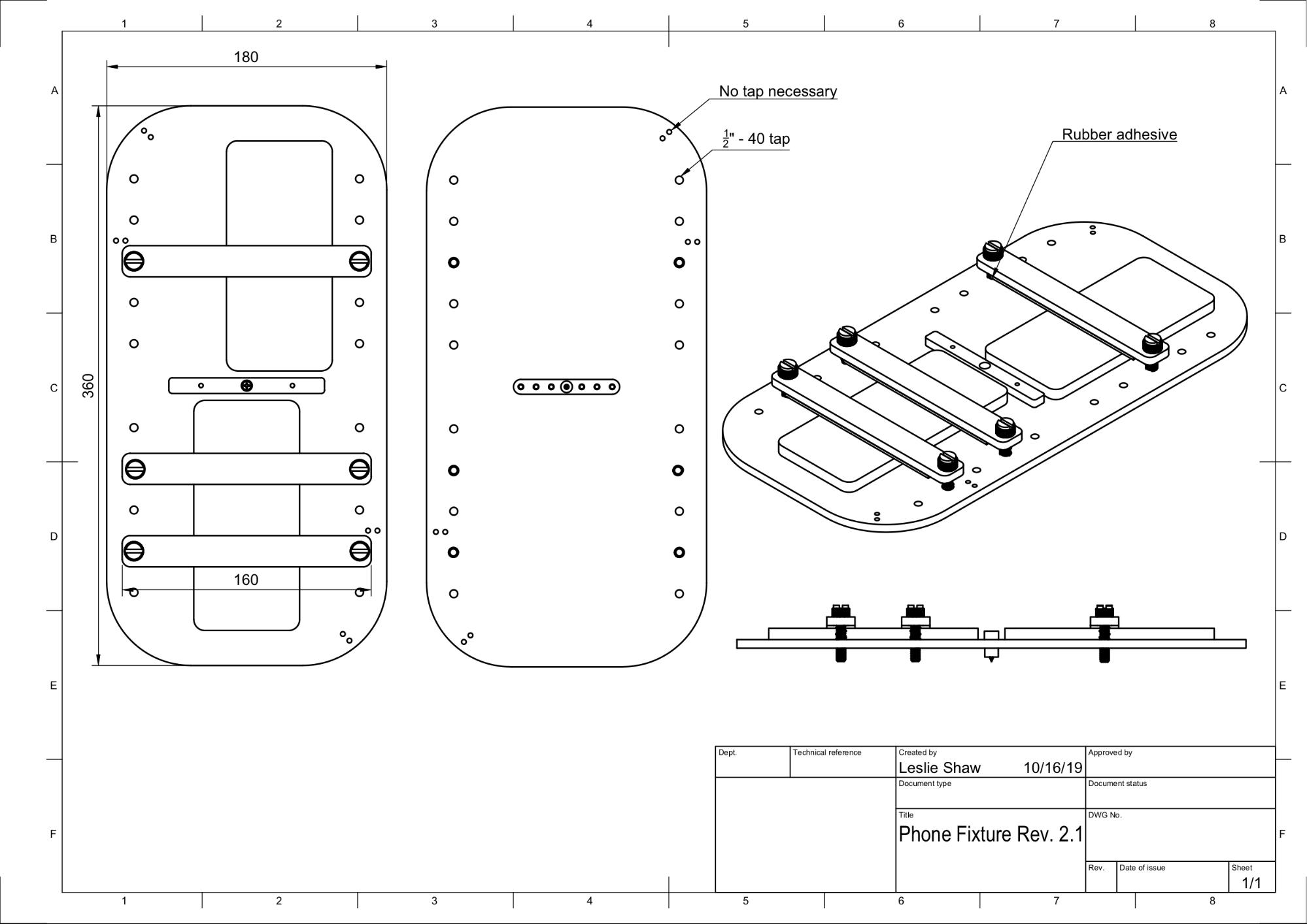
شکل 11. ترسیم مکانیکی فیکسچر تلفن
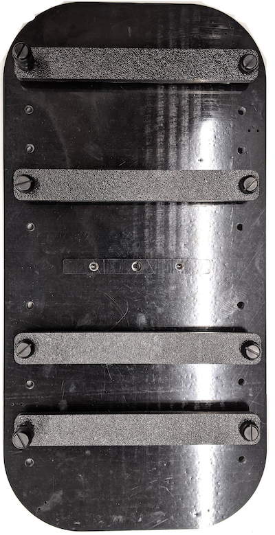
شکل 12. دستگاه تلفن مونتاژ شده
مرحله 4: ریل درب کشویی را مونتاژ کنید
ریل های پانل کشویی را در بالا و پایین جعبه به سمت جلو ثابت کنید. شکل 13 6-32 پیچ را روی سوراخ های از پیش ضربه خورده نشان می دهد. از طرف دیگر، می توانید از پیچ های خودکار استفاده کنید.
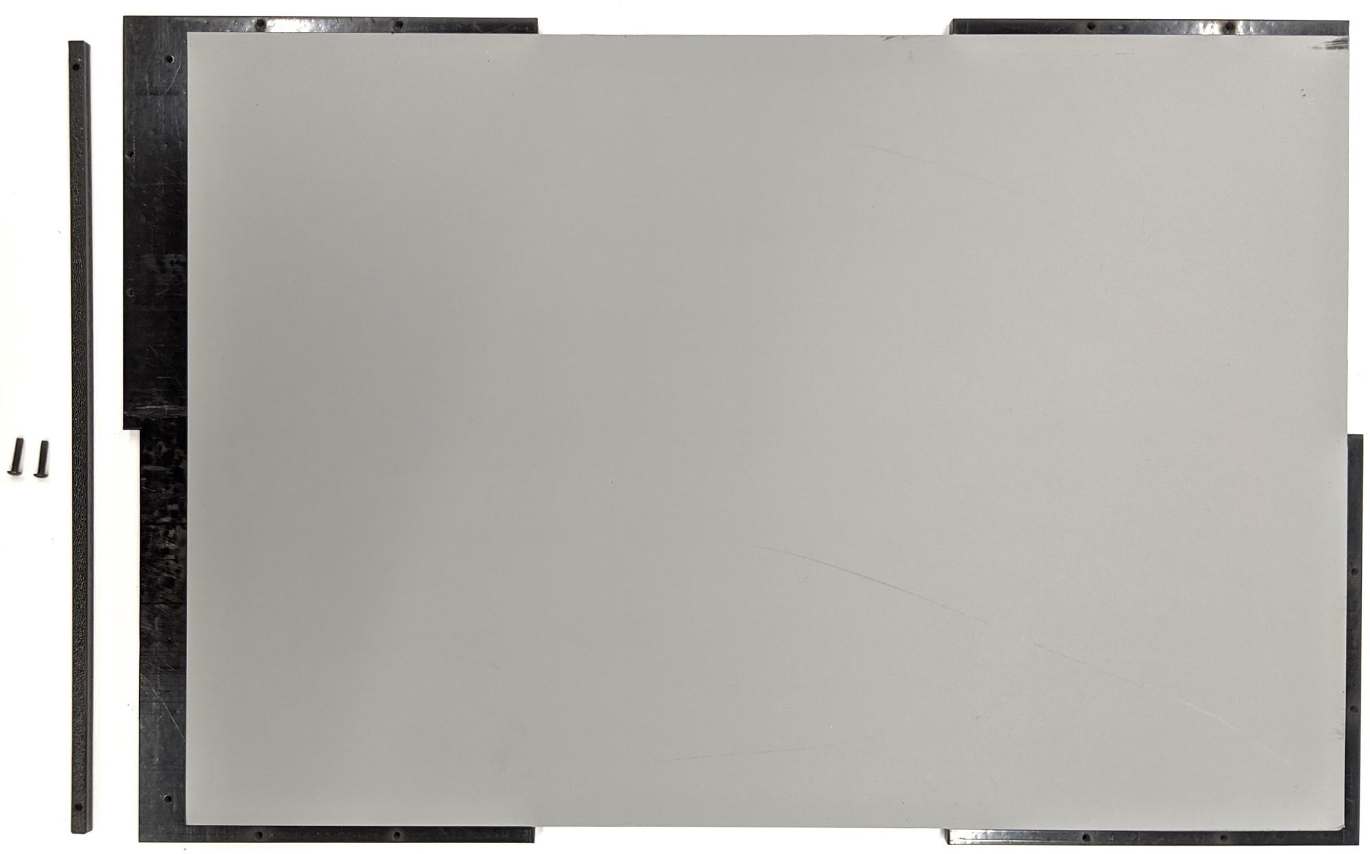
شکل 13. ریل پانل کشویی ثابت در بالا و پایین جعبه
مرحله 5: نور را وصل کنید
برای اتصال براکت های نور و دیفیوزر:
دو قطعه دسته را روی هم قرار دهید و آنها را با استفاده از 6-32 پیچ (یا از پیچ های خودکار) مونتاژ کنید.
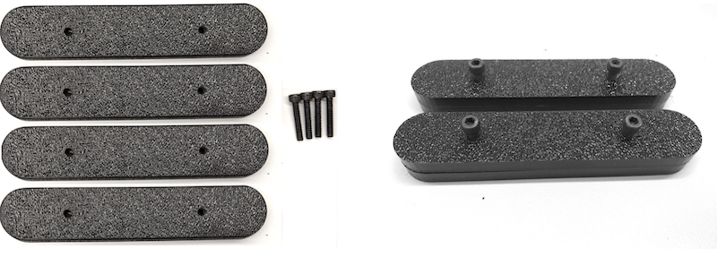
شکل 14. قطعات دسته و مجموعه جعبه فیوژن سنسور
چهار پیچ، مهره و مهره بلوط 4-40 را برای ثابت کردن براکت نصب از کیت روشنایی به دیوار جعبه آماده کنید.
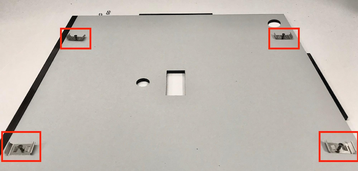
شکل 15. 4-40 پیچ و براکت نور روی دیوار داخلی جعبه
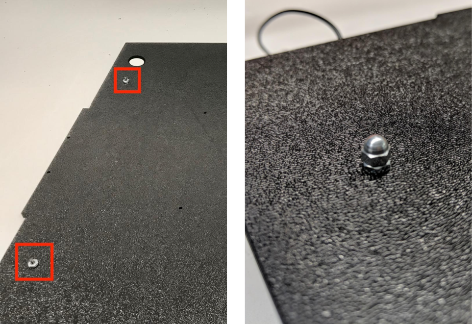
شکل 16. پیچ و مهره های بلوط روی پیچ ها از قسمت بیرونی جعبه اعمال می شود.
پخش کننده نور را به اندازه مناسب برش دهید تا نوارهای نور را بپیچید (اگر چراغ ها همراه با پخش کننده هستند لازم نیست).
شکل 17. نوارهای نور و پخش کننده های نور
پخش کننده نور را دور نوار بپیچید و آن را در پشت بچسبانید.
شکل 18. نوارهای نور و پخش کننده های نور از پشت چسبانده شده اند
چراغ ها را در براکت ها بچسبانید (می تواند محکم باشد).
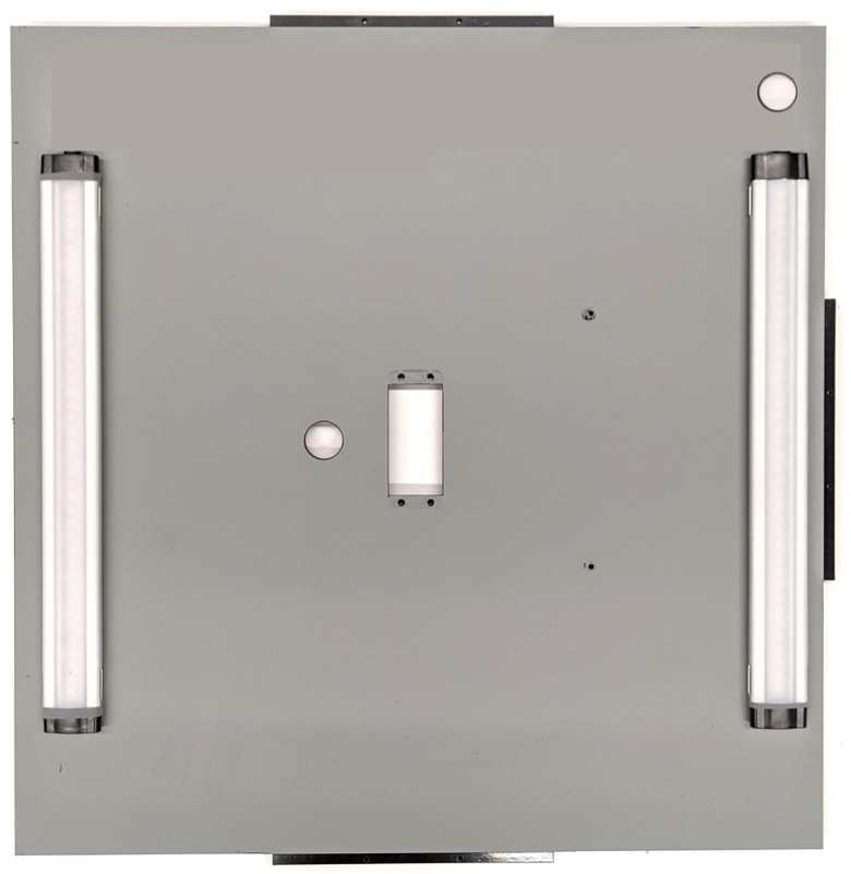
شکل 19. چراغ های نصب شده در براکت ها
مرحله 6: دستگاه تلفن را به صفحه سروو وصل کنید
برای اتصال فیکسچر تلفن به صفحه سروو:
چهار پیچ 6-32 و یک صفحه سروو برای ثابت کردن سروو روی دیوار آماده کنید. سروو را روی دیوار داخلی ثابت کنید و پیچ ها را از داخل داخل صفحه سرو روی دیوار بیرونی قرار دهید.
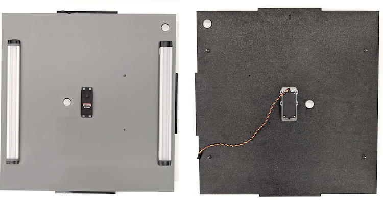
شکل 20. صفحه سروو و سروو با 6-32 پیچ در جای خود نگه داشته می شوند
فیکسچر تلفن را با نایلاک روی سروو محکم کنید (مرکز شفت را به مرکز چرخش سروو فشار دهید).
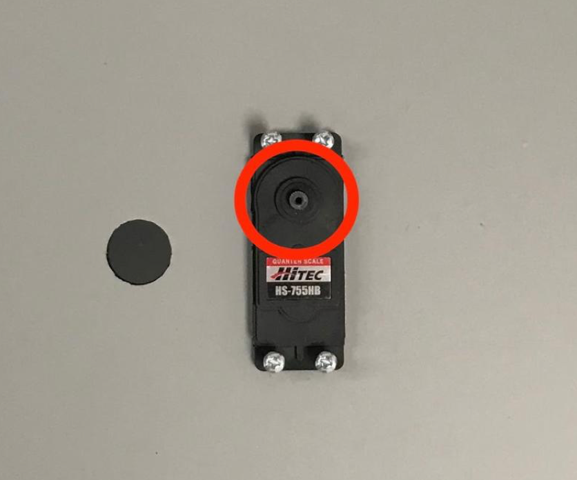
شکل 21. دنده سروو
با استفاده از پیچ سروو که به همراه سروو ارائه شده است، فیکسچر تلفن (1.2 N*m یا 8.9 اینچ*lbf) را از طریق بازوی سروو روی چرخ دنده سروو بپیچید.
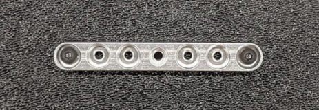
شکل 22. بازوی سرو
مرحله 7: مونتاژ نهایی
برای کامل مونتاژ جعبه فیوژن سنسور:
از اندروید 13، دستگاه تست فیوژن سنسور با کنترلر روشنایی آردوینو اندروید 13 عرضه می شود. (در اندروید 12 یا پایینتر، دستگاه فیوژن سنسور با یک کنترلکننده آردوینو 6 کانالی یا یک کنترلکننده Canakit ارسال میشود. دستگاههای دارای Android 11 تا Android 12 با کنترلکننده Android 13، کنترلکننده Arduino 6 کانال یا کنترلکننده Canakit سازگار هستند.) سروو را به هر کانالی که با سیم مشکی ND مربوط به کنترلر سروو VCC مربوط میشود، وصل کنید. سیم، و SIG مربوط به سیم زرد است.
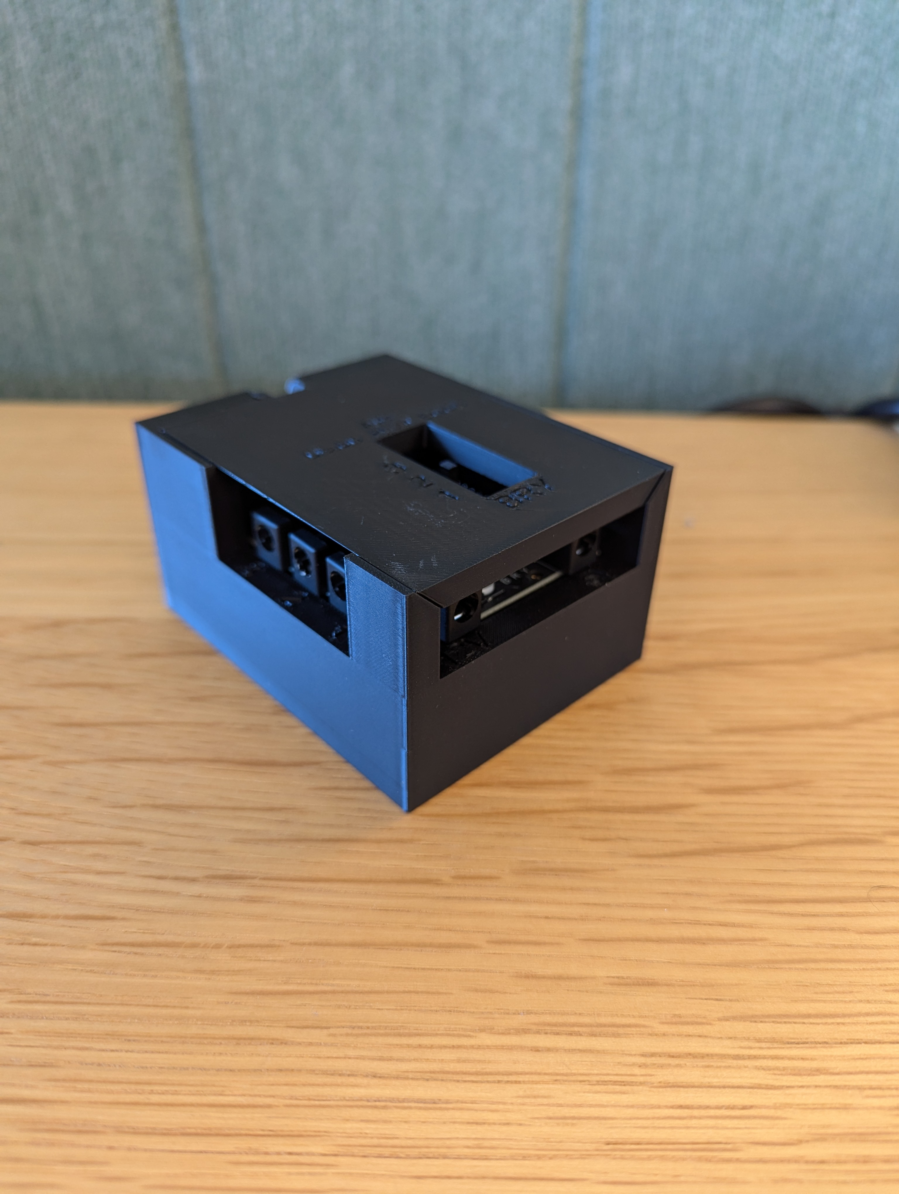
شکل 23. Arduino Lighting Controller Rev3
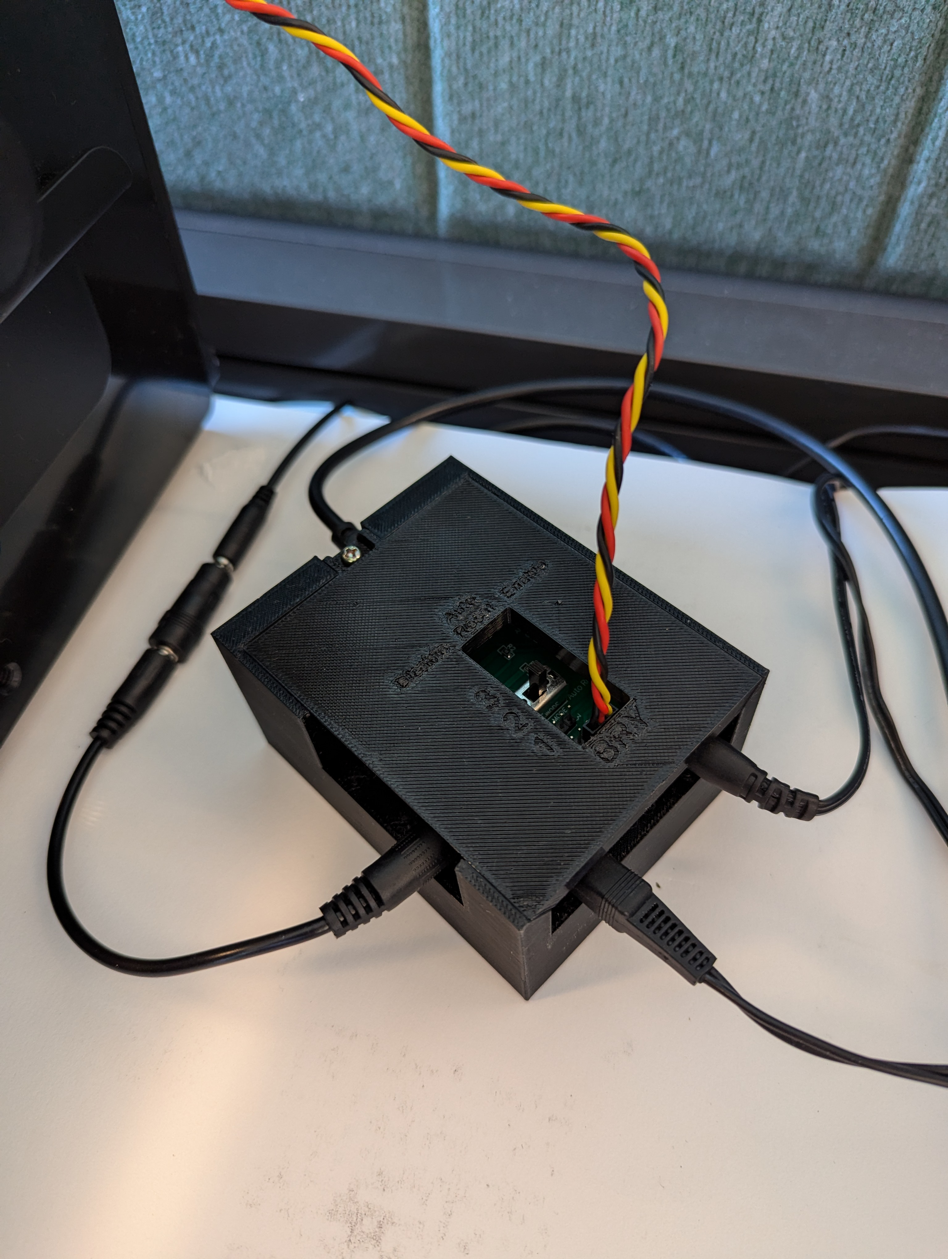
شکل 24. نمونه اتصال کنترلر روشنایی آردوینو Rev3
جعبه را به هم بچسبانید، سپس قطعات را به هم بچسبانید (ممکن است لازم باشد در برخی از قسمت ها از قبل سوراخ کنید).
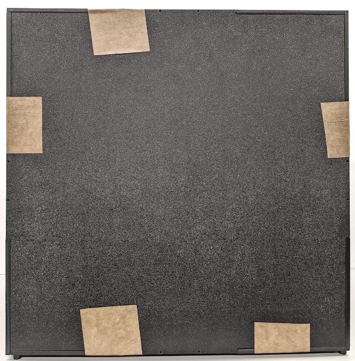
شکل 25. دکل تست همجوشی سنسور نواری
برای Android 15 یا بالاتر، با چاپخانه محلی خود کار کنید تا فایل checkerboard.pdf (که در فهرست test/sensor_fusion پایگاه کد موجود است) را روی کاغذ 18 × 18 اینچی با الگوی شطرنجی به عرض کاغذ چاپ کنید و نمودار را روی دیوار روبروی دستگاه تلفن بچسبانید.
برای دوربینهایی با میدان دید کوچکتر، مانند دوربینهای تلهفوتو، با چاپخانه محلیتان کار کنید تا نسخههایی از صفحه شطرنجی با مقیاس متناسب ایجاد کنید. (به عنوان مثال، یک نمودار با مقیاس 50٪ روی کاغذ 9 در 9 اینچ چاپ می شود.)
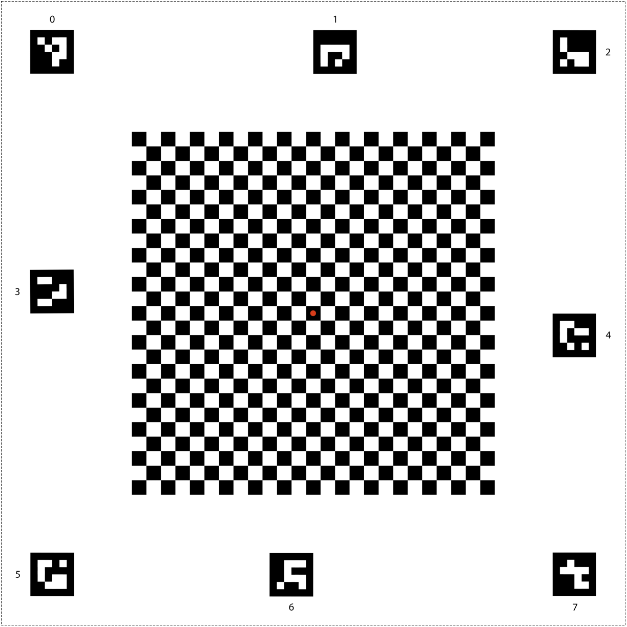
شکل 26. نمودار شطرنجی برای اندروید 15 یا بالاتر.
همانطور که در شکل 27 نشان داده شده است، اطمینان حاصل کنید که نقطه قرمز در مرکز شطرنجی هنگامی که روی فیکسچر قرار می گیرد، مستقیماً رو به دوربین باشد.
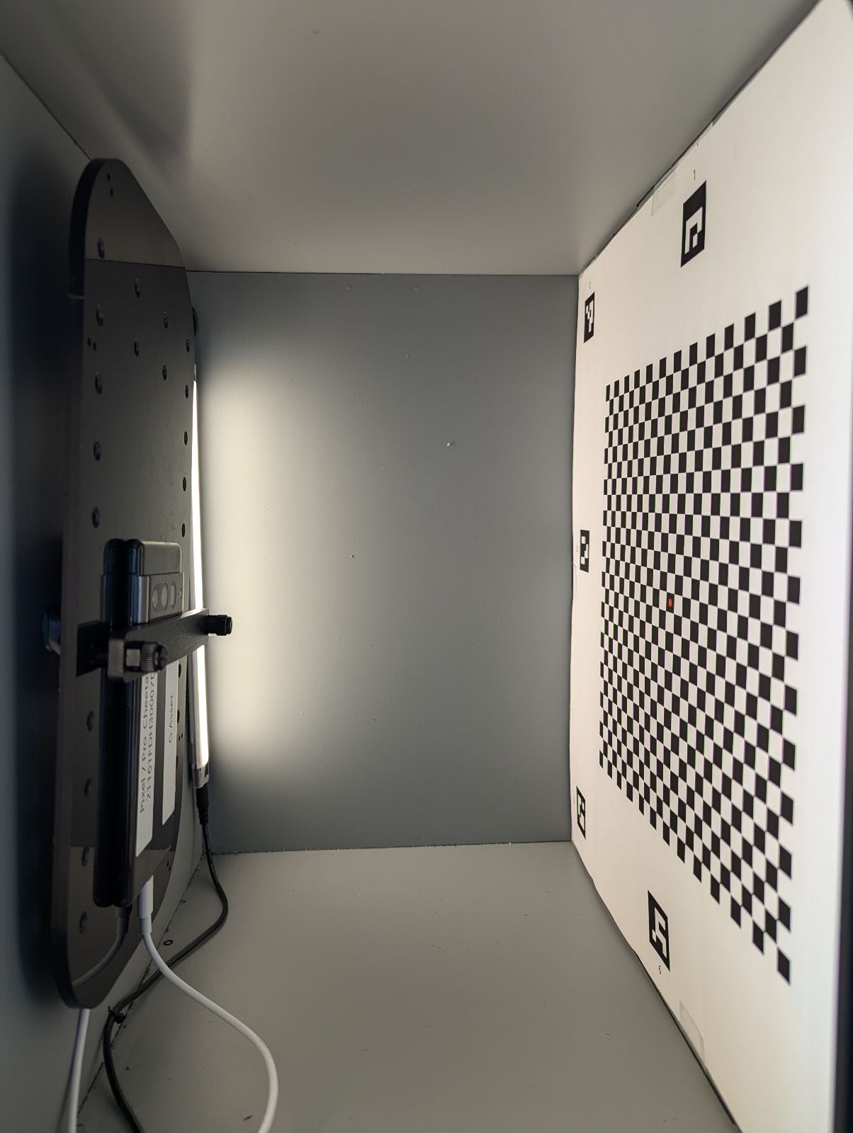
شکل 27. تخته شطرنجی چاپ شده و به دیوار مقابل دستگاه تلفن چسبانده شده است.
محتوا و نمونه کدها در این صفحه مشمول پروانههای توصیفشده در پروانه محتوا هستند. جاوا و OpenJDK علامتهای تجاری یا علامتهای تجاری ثبتشده Oracle و/یا وابستههای آن هستند.
تاریخ آخرین بهروزرسانی 2025-07-30 بهوقت ساعت هماهنگ جهانی.
[[["درک آسان","easyToUnderstand","thumb-up"],["مشکلم را برطرف کرد","solvedMyProblem","thumb-up"],["غیره","otherUp","thumb-up"]],[["اطلاعاتی که نیاز دارم وجود ندارد","missingTheInformationINeed","thumb-down"],["بیشازحد پیچیده/ مراحل بسیار زیاد","tooComplicatedTooManySteps","thumb-down"],["قدیمی","outOfDate","thumb-down"],["مشکل ترجمه","translationIssue","thumb-down"],["مشکل کد / نمونهها","samplesCodeIssue","thumb-down"],["غیره","otherDown","thumb-down"]],["تاریخ آخرین بهروزرسانی 2025-07-30 بهوقت ساعت هماهنگ جهانی."],[],[],null,["# Obtain a sensor fusion box\n\nThis page provides information on how to purchase or assemble a Sensor Fusion\nBox. The Sensor Fusion Box is used in the CameraITS `sensor_fusion` test and\n`multi-camera` sync test. It provides a consistent test environment for\nmeasuring timestamp accuracy of sensors for Android\ndevices, specifically camera image sensors and gyroscopes. It consists of\nplastic box components that are laser cut from\ncomputer-aided design (CAD) drawings and a Servo Control Box.\n\nYou can purchase a Sensor Fusion Box or build your own.\n\nPurchase a Sensor Fusion Box\n----------------------------\n\nWe recommend purchasing a Sensor Fusion Box from one of the following qualified\nvendors.\n\n- *Byte Bridge Inc.* \n\n USA: 1502 Crocker Ave, Hayward, CA 94544-7037 \n\n China: 22F #06-08, Hongwell International Plaza Tower A,\n 1600 West Zhongshan Road, Xuhui, Shanghai, 200235 \n\n [www.bytebt.com](https://www.bytebt.com/) \n\n androidpartner@bytebt.com \n\n USA: +1-510-373-8899 \n\n China: +86-400-8866-490\n\n- *JFT CO LTD 捷富通科技有限公司 (previously known as MYWAY DESIGN)* \n\n China: No. 40, Lane 22, Heai Road, Wujing Town, Minhang District, Shanghai, China \n\n Taiwan: 4F., No. 163, Fu-Ying Road, XinZhuang District, New Taipei City 242, Taiwan \n\n [www.jftcoltd.com](https://www.jftcoltd.com) \n\n service@jfttec.com or its.sales@jfttec.com \n\n China:+86-021-64909136 \n\n Taiwan: 886-2-29089060\n\n| **Note:** For additional support for foldable and large form factor devices, you can purchase the [foldable kit](/docs/compatibility/cts/its-accessories-foldable-kit).\n\nBuild a Sensor Fusion Box\n-------------------------\n\nThis section includes step-by-step instructions for assembling a Sensor Fusion\nBox from laser-cut acrylonitrile butadiene styrene (ABS) components (shown in\nFigure 1).\n\n\u003cbr /\u003e\n\n\n**Figure 1.** Mechanical drawing of Sensor Fusion Box components\n\n### Required tools\n\nBefore starting, ensure you have downloaded the technical drawings for the\nSensor Fusion Box (included in the\n[Sensor Fusion Box zip file](/static/docs/compatibility/cts/sensor_fusion_1_8.zip))\nand have the following tools available:\n\n- Phillips head screwdriver\n- JIS head screwdriver\n- Hex keys\n- Power drill set\n- X-ACTO knife\n- Tape\n\n### Step 1: Apply vinyl stickers\n\nAfter creating the ABS components with a laser\ncutter, apply vinyl stickers to the plastic box to get the proper color control\non the interior of the test box:\n\n1. Apply vinyl on the smooth side of the ABS\n as shown in Figure 2. For helpful tips on applying vinyl, refer to\n [wikiHow](https://www.wikihow.com/Install-a-Vinyl-Graphic).\n\n2. Cut out the necessary holes on the vinyl with the exacto knife.\n\n \u003cbr /\u003e\n\n\n **Figure 2.** ABS pieces with vinyl applied on the smooth side (interior of\n the box)\n3. Using acrylic glue, glue the round ABS pieces onto the four corners of the\n bottom panel.\n\n \u003cbr /\u003e\n\n\n **Figure 3.** Bottom panel with round ABS pieces glued to the four corners.\n\n### Step 2: Prepare phone mount and attach servo mount\n\nTo prepare the phone mount to attach to the servo:\n\n1. Tap 20 holes on the phone fixture with a 1/4\"-20 drill bit.\n\n \u003cbr /\u003e\n\n\n **Figure 4.** Phone fixture with tapped holes\n2. Make sure you have the ABS cut outs, nylon thumb screws, nylon nuts\n (for adjusting screw height if necessary), the C1 spline\n actobotics dual servo arm, 4-40 screws, and compression springs.\n\n \u003cbr /\u003e\n\n\n **Figure 5.** Phone mount parts\n3. Apply the 4-40 screws and tighten (1.2 N\\*m or 8.9 in\\*lbf) the\n servo arm to the back of the phone mount. Using the same screws and\n 4-40 cap nuts, tighten the phone divider ABS cut out on the front side of\n the phone mount.\n\n \u003cbr /\u003e\n\n\n **Figure 6.** Shaft on the back of fixture, tightened by screws applied\n from the front\n\n \u003cbr /\u003e\n\n\n **Figure 7.** 4-40, 3/4\" long screws and 4-40 cap nuts\n\n \u003cbr /\u003e\n\n\n **Figure 8.** Back (left) and front (right) of the phone mount\n\n### Step 3: Attach phone clamps\n\nTo attach the phone clamps:\n\n1. Cut the neoprene sheet according to the shape of the ABS cut-out\n clamps, but leave one inch shorter from both ends as shown in Figure 9.\n After cutting the neoprene sheet accordingly, apply the pieces to the ABS\n cut-out clamps as in Figure 8.\n\n \u003cbr /\u003e\n\n\n **Figure 9.** ABS clamp with neoprene sheet applied\n2. Attach nylon thumb screws and spring wire to the clamp. Add nylon\n nuts to reduce screw length, as needed.\n\n \u003cbr /\u003e\n\n\n **Figure 10.** Clamp with neoprene sheet, thumb screws, nylon nuts, and\n spring wire\n3. Screw the phone clamps' thumb screws into the tapped holes of the phone\n fixture as shown in Figure 11. You can adjust the location of the phone\n mounts depending on the size of the phones.\n\n \u003cbr /\u003e\n\n\n **Figure 11.** Mechanical drawing of the phone fixture\n\n \u003cbr /\u003e\n\n\n **Figure 12.** Assembled phone fixture\n\n### Step 4: Assemble sliding door rail\n\n1. Fix sliding panel rails on the top and bottom of the box toward the front.\n Figure 13 shows 6-32 screws on pre-tapped holes. Alternatively, you can use\n self-tapping screws.\n\n \u003cbr /\u003e\n\n\n **Figure 13.** Fixed sliding panel rail on top and bottom of box\n\n### Step 5: Attach lighting\n\nTo attach the light brackets and diffuser:\n\n1. Stack two handle pieces on top of each other and assemble them using 6-32\n screws (or use self-tapping screws).\n\n \u003cbr /\u003e\n\n\n **Figure 14.** Sensor Fusion Box handle pieces and assembly\n2. Prepare four 4-40 screws, nuts, and acorn nuts to fix the mounting bracket\n from the lighting kit to the wall of the box.\n\n \u003cbr /\u003e\n\n\n **Figure 15.** 4-40 screws and light bracket on the interior wall of the box\n\n \u003cbr /\u003e\n\n\n **Figure 16.** Bolts and acorn bolts applied to the screws from the exterior\n of the box\n3. Cut the light diffuser to an appropriate size to wrap the light strips (not\n required if the lights come with the diffuser).\n\n \u003cbr /\u003e\n\n\n **Figure 17.** Light strips and light diffusers\n4. Wrap the light diffuser around the strip and tape it at the back.\n\n \u003cbr /\u003e\n\n\n **Figure 18.** Light strips and light diffusers taped from the back\n5. Snap the lights into the brackets (can be a tight fit).\n\n \u003cbr /\u003e\n\n\n **Figure 19.** Lights mounted in brackets\n\n### Step 6: Attach phone fixture to servo plate\n\nTo attach the phone fixture to the servo plate:\n\n1. Prepare four 6-32 screws and a servo plate to fix the servo onto the wall.\n Fix the servo onto the interior wall and insert the screws from the inside\n into the servo plate on the exterior wall.\n\n \u003cbr /\u003e\n\n\n **Figure 20.** Servo and servo plate held in place with 6-32 screws\n2. Secure the phone fixture onto the servo with nylocks (pushing the center of the\n shaft into the servo's rotation center).\n\n **Figure 21.** Servo gear\n3. Using the servo screw that came with the servo, screw (1.2 N\\*m or\n 8.9 in\\*lbf) the phone fixture onto the servo gear through the servo\n arm.\n\n **Figure 22.** Servo arm\n\n### Step 7: Final assembly\n\nTo complete assembly of the Sensor Fusion Box:\n\n1. From Android 13, the sensor fusion test rig comes\n with the\n [Android 13 Arduino lighting controller](/docs/compatibility/cts/sensor-fusion-controller).\n (In Android 12\n or lower, the sensor fusion rig shipped with a 6-channel Arduino\n controller or a Canakit controller. Devices running\n Android 11 to Android 12\n are compatible with the Android 13 controller, 6-channel Arduino controller,\n or Canakit controller.) Connect the servo extension to any channel of the\n servo controller, where GND corresponds to black wire, VCC corresponds to\n the red wire, and SIG corresponds to the yellow wire.\n\n \u003cbr /\u003e\n\n\n **Figure 23.** Arduino Lighting Controller Rev3\n\n \u003cbr /\u003e\n\n\n **Figure 24.** Arduino lighting controller Rev3 connection sample\n2. Tape the box together, then screw the parts together (you might need to\n pre-drill holes in some parts).\n\n **Figure 25.** Taped sensor fusion test rig\n3. For Android 15 or higher, work with your local print\n shop to print out the checkerboard.pdf file (included in the\n `test/sensor_fusion` directory of the codebase)\n on 18 x 18 inch paper with the checkerboard pattern the width of the paper,\n and tape the chart on the wall opposite the phone fixture.\n\n For cameras with smaller fields of view, such as telephoto cameras, work\n with your local print shop to create proportionally scaled versions of the\n checkerboard. (For example, a 50% scaled chart would be printed on 9 x 9\n inch paper.)\n\n **Figure 26.** Checkerboard chart for Android 15 or\n higher.\n\n Make sure the red dot in the center of the checkerboard is directly facing\n the camera when placed on the fixture, as shown in Figure 27.\n\n **Figure 27.** Checkerboard printed and taped to the opposite wall of phone\n fixture."]]