קל לארגן דפים בעזרת אוספים
אפשר לשמור ולסווג תוכן על סמך ההעדפות שלך.
בבדיקה של שילוב החיישנים נמדדת הדיוק של חותמת הזמן של חיישנים במכשירי Android, במיוחד חיישני תמונה של מצלמות וחיישנים גירוסקופיים. בדף הזה מפורטות הוראות מפורטות להגדרת הבדיקה של Sensor Fusion ו-Sensor Fusion Box בפעם הראשונה.
סרטון הדרכה
סרטון הדרכה על הגדרת Sensor Fusion Box.
כלים נדרשים
לפני שמתחילים, חשוב לוודא שיש לכם את הרכיבים הבאים:
איור 1. הרכיבים הנדרשים לבדיקת מיזוג החיישנים
כבל USB A ל-B
כבל USB A ל-C (לטלפון לבדיקה)
כבל חשמל 12V 2A (לקופסת הבקרה של המנועים הסורבו)
כבל חשמל 12V (לתאורה, עם מתג)
כבל חיבור זכר-זכר 5V (לתאורה)
כבל המרה זכר-נקבה 5V (לתאורה)
שלב 1: חיבור הנורות
כדי לחבר את האורות:
משתמשים בכבל זכר-זכר כדי לחבר את שתי הנורות בקצוות התחתונים שלהן, כפי שמוצג באיור 2. מקבעים את הכבל לתחתית התיבה כדי שהוא לא יפריע לפעולה.
מחברים את הקצה של הנורה הקרוב יותר ליציאה של כבל התאורה לכבל ההמרה
איור 2. חיבור הנורות זו לזו ואחת מהן לכבל ההמרה
חור יציאה של כבל אור
חור יציאה של כבל USB
כבל המרה זכר-זכר 5V
מחברים את הקצה הלא מחובר של כבל ההמרה דרך החור העגול בחלק העליון של התיבה, ואז מחברים אותו לכבל החשמל של התאורה.
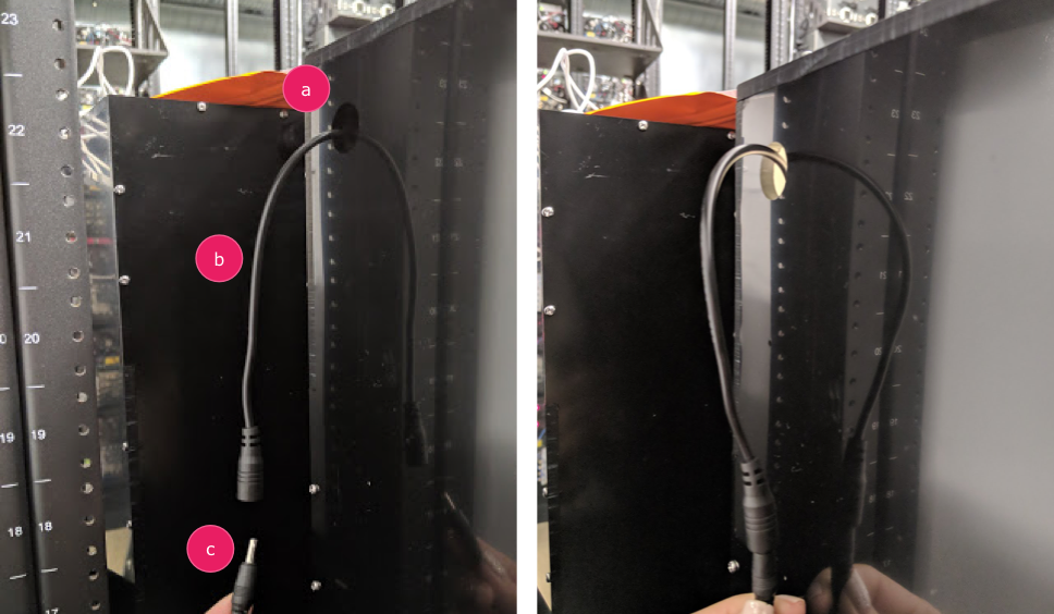
איור 3. כבל ההמרה של Lighting יוצא מהקופסה ומחובר לכבל החשמל
חור יציאה
כבל המרה
כבל חשמל
שלב 2: מחברים את המנוע הסרבו
כדי לחבר את המנוע החשמלי:
מחברים את מחבר הסרבו לבורר הסרבו. חשוב להכניס את המחבר כך שהצבעים יהיו באותו כיוון כמו בתוויות (Y = צהוב, R = אדום, B = שחור), כי היפוך הסדר עלול לגרום נזק למנוע. אם הכבל קצר מדי, צריך להשתמש ב
כבל הארכה לסרוו.
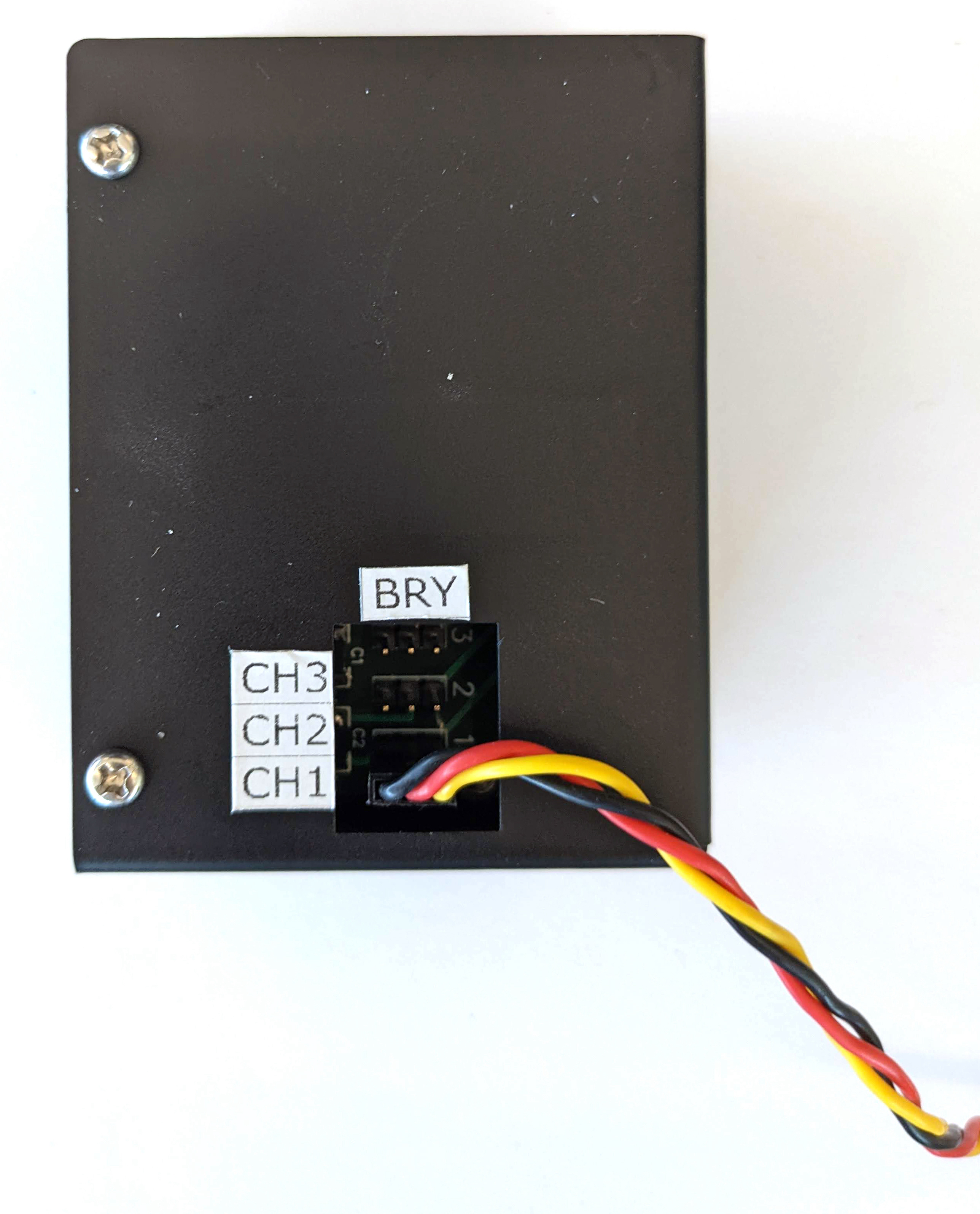
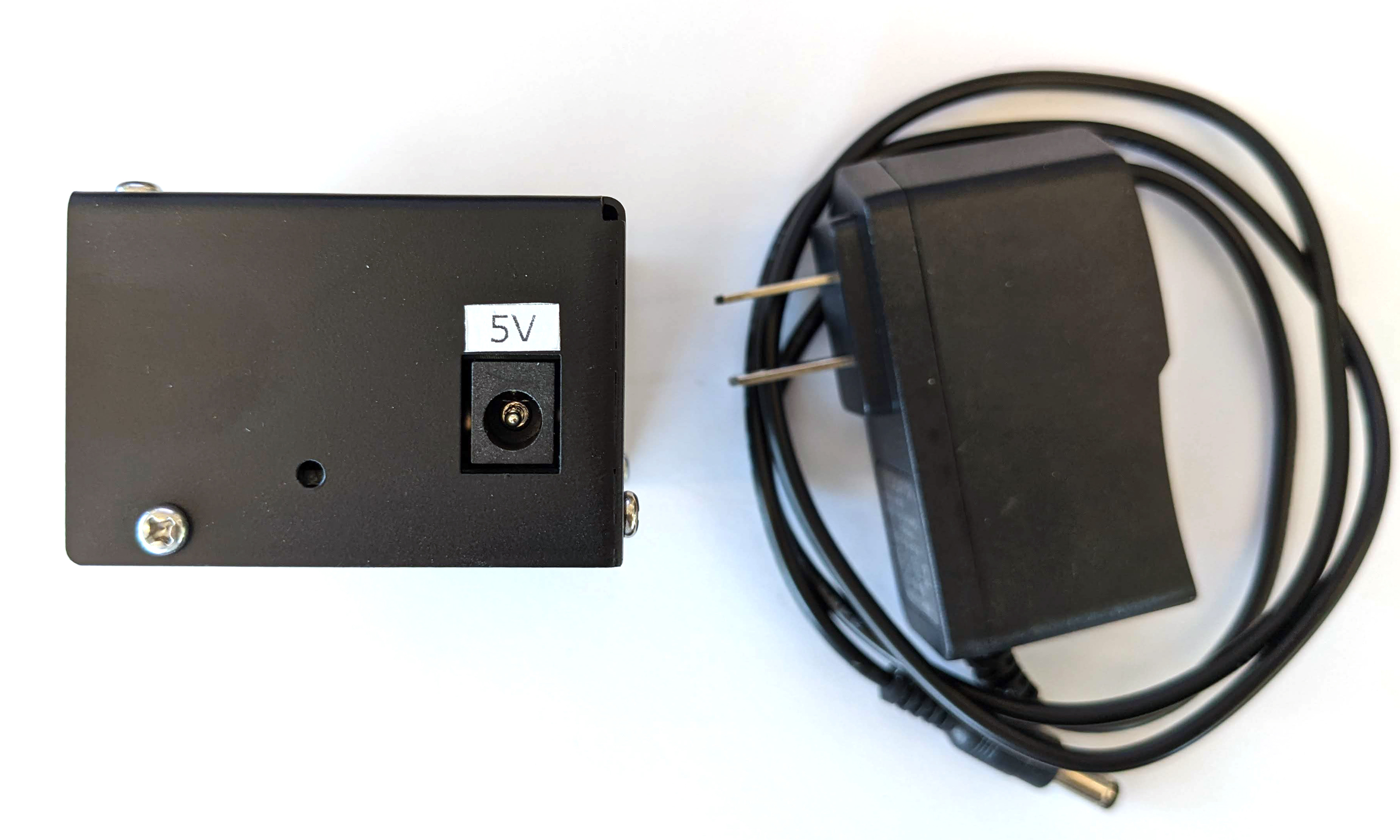
איור 4. חיבור של סרוו לתיבת הבקרה של הסרוו
מחברים את בקר הסרוו באמצעות כבל החשמל שלו (לתאורת ה-LED ולבקר הסרוו יש מקורות חשמל נפרדים ומסוגים שונים).
איור 5. חיבור של אמצעי הבקרה של הסרבו לכבל החשמל הייעודי שלו
משתמשים בכבל USB A ל-B כדי לחבר את תיבת הבקרה של הסרוו למארח (המכונה שבה פועל הבדיקה).
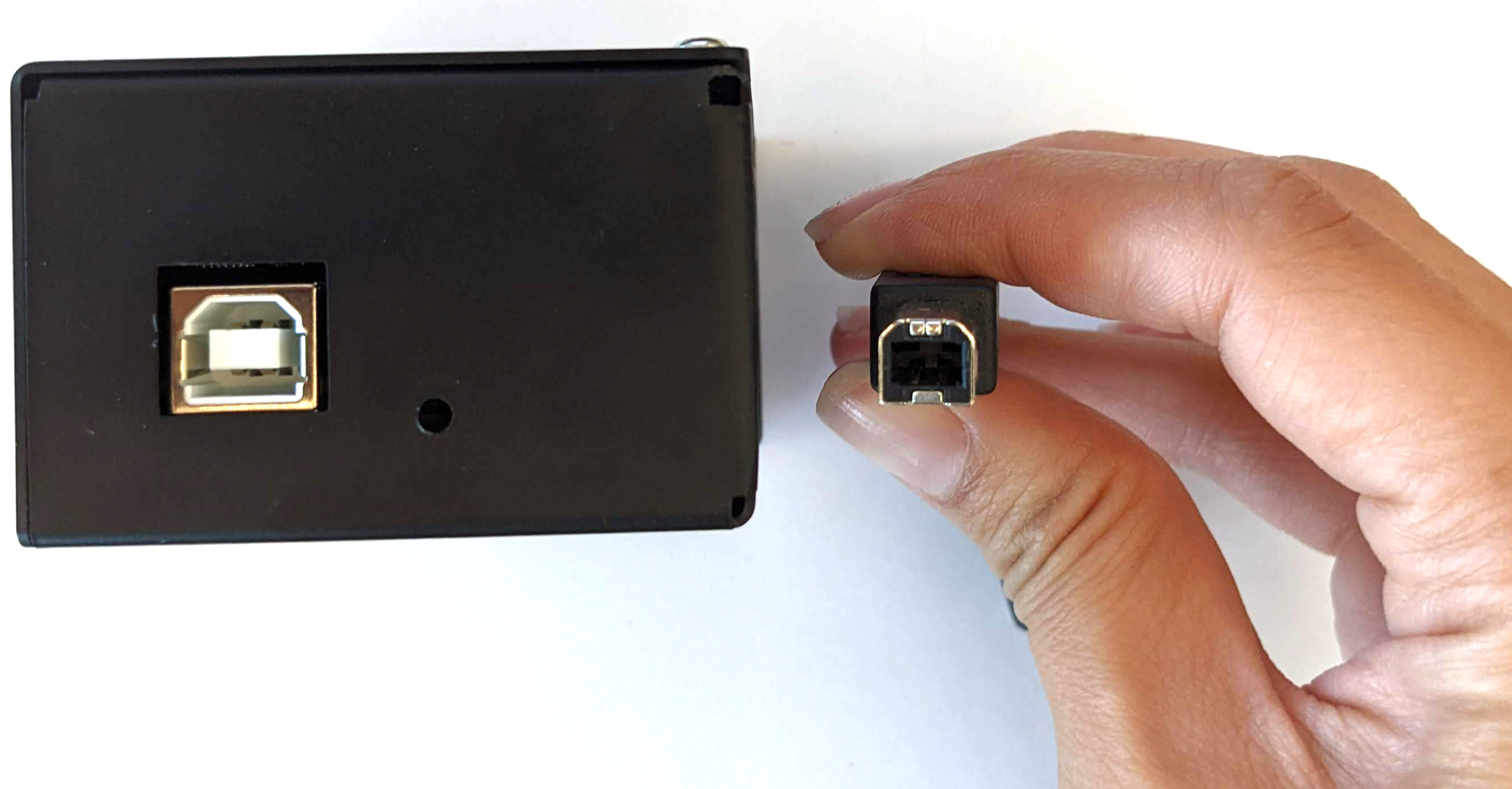
איור 6. חיבור של תיבת הבקרה של הסרבו למכונה המארחת
שלב 3: מחברים את הטלפון
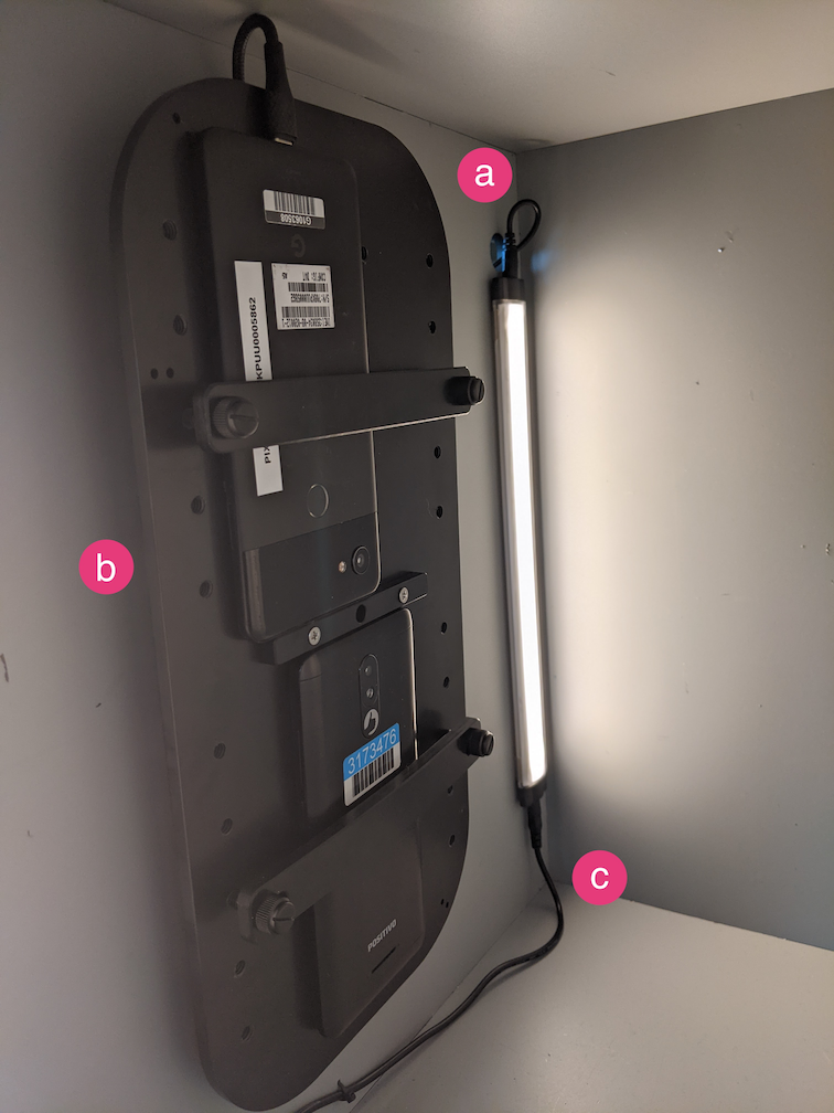
מניחים את הטלפון על המתקן ומצמידים אותו. מבריגים את בורג הנילון ימינה. 
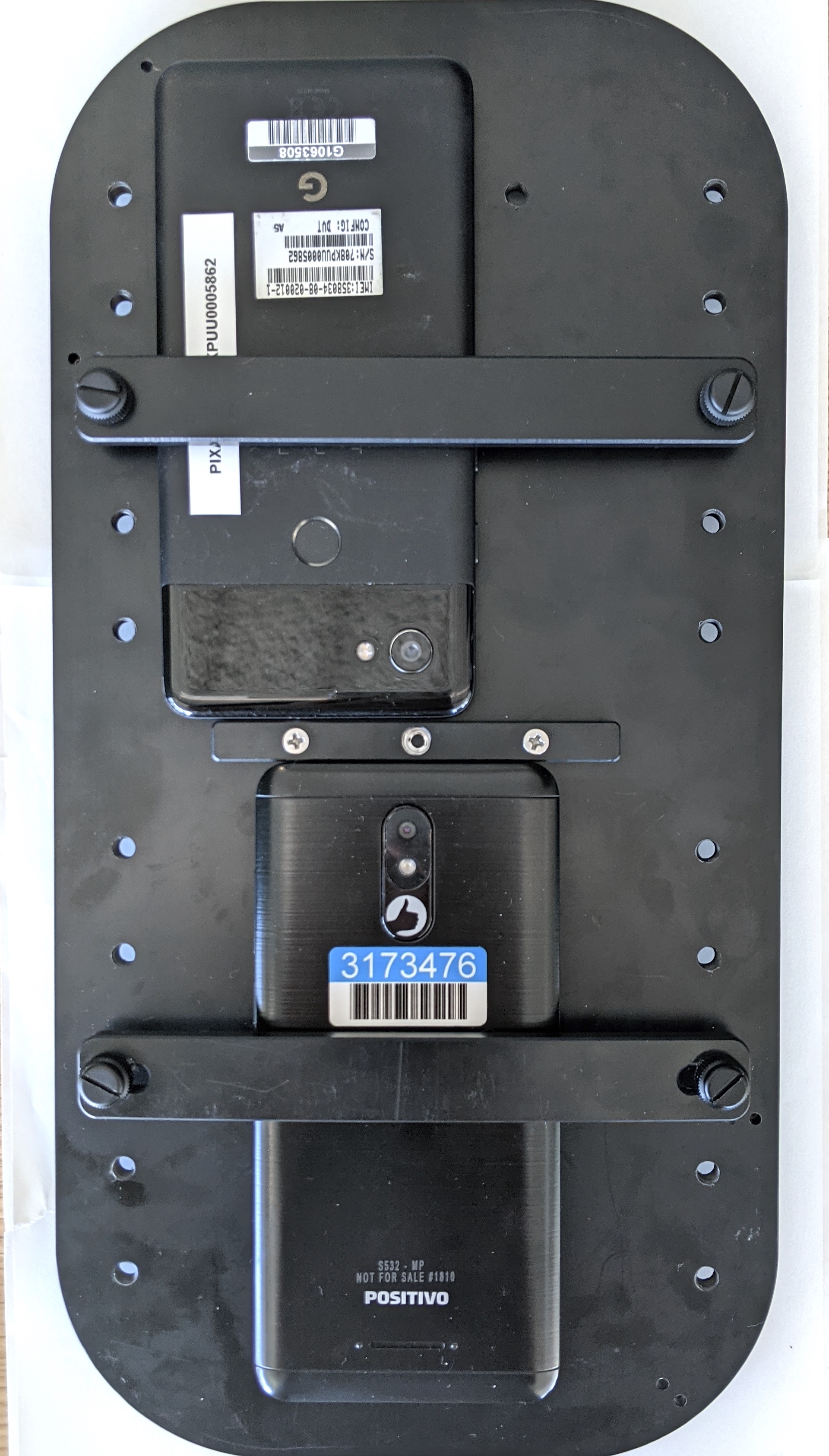
איור 7. הצבת הטלפון במתקן והצמדת הטלפון למתקן
צריך למקם את הטלפונים כך שכבלי ה-USB יהיו בפריפריה של מעמד הטלפון והמצלמות יהיו ליד מרכז המעמד.
משתמשים בכביסן כדי לחבר את כבל ה-USB של הטלפון ללוחית המכשיר ולהוביל אותו מחוץ לקופסה דרך פתח היציאה. מחברים את הקצה השני של הכבל למארח שבו מריצים את הבדיקה.
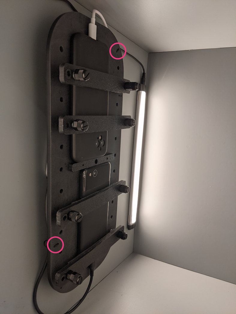
איור 8. כבל USB של טלפון שמחובר למתקן באמצעות כבלים
כדי לפתור בעיות שקשורות להרשאות לצורך שליטה במנוע דרך יציאת ה-USB:
מוסיפים את שם המשתמש של המפעיל לקבוצה dialout באמצעות:
sudo adduser USERNAME dialout
ניתוק המפעיל מהמערכת.
מתחברים לאופרטורים.
דוגמאות התוכן והקוד שבדף הזה כפופות לרישיונות המפורטים בקטע רישיון לתוכן. Java ו-OpenJDK הם סימנים מסחריים או סימנים מסחריים רשומים של חברת Oracle ו/או של השותפים העצמאיים שלה.
עדכון אחרון: 2025-07-30 (שעון UTC).
[[["התוכן קל להבנה","easyToUnderstand","thumb-up"],["התוכן עזר לי לפתור בעיה","solvedMyProblem","thumb-up"],["סיבה אחרת","otherUp","thumb-up"]],[["חסרים לי מידע או פרטים","missingTheInformationINeed","thumb-down"],["התוכן מורכב מדי או עם יותר מדי שלבים","tooComplicatedTooManySteps","thumb-down"],["התוכן לא עדכני","outOfDate","thumb-down"],["בעיה בתרגום","translationIssue","thumb-down"],["בעיה בדוגמאות/בקוד","samplesCodeIssue","thumb-down"],["סיבה אחרת","otherDown","thumb-down"]],["עדכון אחרון: 2025-07-30 (שעון UTC)."],[],[],null,["# Test sensor fusion\n\nThe sensor fusion test measures timestamp accuracy of sensors for\nAndroid devices, specifically camera image sensors and gyroscopes. This\npage provides step-by-step directions on\nhow to setup the Sensor Fusion test and Sensor Fusion Box for the first\ntime.\n\nVideo tutorial\n--------------\n\n\nThis is a video tuturial on how to set up the sensor fusion box. \n\nRequired tools\n--------------\n\n\nBefore getting started, ensure you have the following components:\n**Figure 1.** Components required for the sensor fusion test\n\n1. USB A to B cable\n2. USB A to C cable (for test phone)\n3. 12V 2A power cord (for servo control box)\n4. 12V power cord (for lighting, with switch)\n5. 5V male-male connection cable (for lighting)\n6. 5V male-female conversion cable (for lighting)\n\nStep 1: Connect lights\n----------------------\n\n\nTo connect the lights:\n\n1. Use the male-male cable to connect the two lights on the bottom ends of the lights as shown in figure 2. Secure the cable to the bottom of the box to keep the cable from interfering with the operation.\n2. Connect the end of the light closer to the light cable exit hole to the conversion cable **Figure 2.** Connecting the lights to each other and one light to the conversion cable\n 1. Light cable exit hole\n 2. USB cable exit hole\n 3. 5V male-male conversion cable\n3. Thread the unconnected end of the conversion cable through the round hole that exits the box, then connect it to the power cable for lighting. **Figure 3.** Lighting conversion cable exiting the box and connecting to power cable\n 1. Exit hole\n 2. Conversion cable\n 3. Power cable\n\nStep 2: Attach servo\n--------------------\n\n\nTo attach the servo:\n\n1. Plug the servo connector into the servo control. Be sure to insert the connector oriented to the corresponding colors as labeled (Y = Yellow, R = Red, B = Black), as reversing the order could damage the motor. If the cord is too short, use a [servo extension cable](https://www.adafruit.com/product/972). **Figure 4.** Servo connecting to the servo control box\n2. Connect the servo control with its power cord (the lighting and servo control have independent, dedicated power supplies). **Figure 5.** Connecting the servo control to its dedicated power cord\n3. Use the USB A to B cable to connect the servo control box to the host (machine that is running the test). **Figure 6.** Connecting the servo control box to the host machine\n\nStep 3: Attach phone\n--------------------\n\n1. Set the phone on the fixture and clamp it down. Tighten by turning the nylon screw right. \n **Figure 7.** Placing and clamping the phone on the fixture\n\n Phones should be placed in a manner where the USB cords are located at\n the periphery of the phone mount and the cameras are near the center of\n the mount.\n2. Use a zip tie to hold the phone USB cord to the fixture plate and lead it outside the box through the exit hole. Plug the other end of the cord to the host running the test. **Figure 8.** Phone USB cord held to fixture with zip ties\n\nStep 4: Run test script\n-----------------------\n\n\nThe main python executable for the test script is: \n\n python tools/run_all_tests.py device=ID camera=0 scenes=sensor_fusion rot_rig=default\n \nYou can modify the command to specify the actual rotator address by using: \n\n```scdoc\nrot_rig=VID:PID:CH\n \n```\n\n- To determine the Vendor ID (VID) and Product ID (PID), use the Linux command `lsusb`.\n- By default, the VID and PID are set to `04d8` and `fc73` with channel \"1\".\n\n### Multiple runs, different formats\n\nTo perform multiple runs with different formats, you can use a\ndifferent script (however, the results will not be uploaded to\n`CtsVerifier.apk`). Sample test script: \n\n python tools/run_sensor_fusion_box.py device=FA7831A00278 camera=0 rotator=default img_size=640,360 fps=30 test_length=7\n\n### Permission issues\n\nTo resolve permission issues related to controlling the motor through the\nUSB port:\n\n1. Add the operator username to the `dialout` group using: \n\n sudo adduser \u003cvar translate=\"no\"\u003eUSERNAME\u003c/var\u003e dialout\n \n2. Log out the operator.\n3. Log in the operator."]]