27 Mart 2025'ten itibaren AOSP'yi derlemek ve AOSP'ye katkıda bulunmak için aosp-main yerine android-latest-release kullanmanızı öneririz. Daha fazla bilgi için AOSP'de yapılan değişiklikler başlıklı makaleyi inceleyin.
Koleksiyonlar ile düzeninizi koruyun
İçeriği tercihlerinize göre kaydedin ve kategorilere ayırın.
Sensör birleştirme testi, Android cihazlardaki sensörlerin (özellikle kamera görüntü sensörleri ve jiroskoplar) zaman damgası doğruluğunu ölçer. Bu sayfada, Sensor Fusion testinin ve Sensor Fusion Box'ın ilk kez nasıl ayarlanacağına dair adım adım talimatlar verilmiştir.
Eğitim videosu
Bu, sensör füzyon kutusunu ayarlamayla ilgili bir eğitim videosudur.
Gerekli araçlar
Başlamadan önce aşağıdaki bileşenlere sahip olduğunuzdan emin olun:
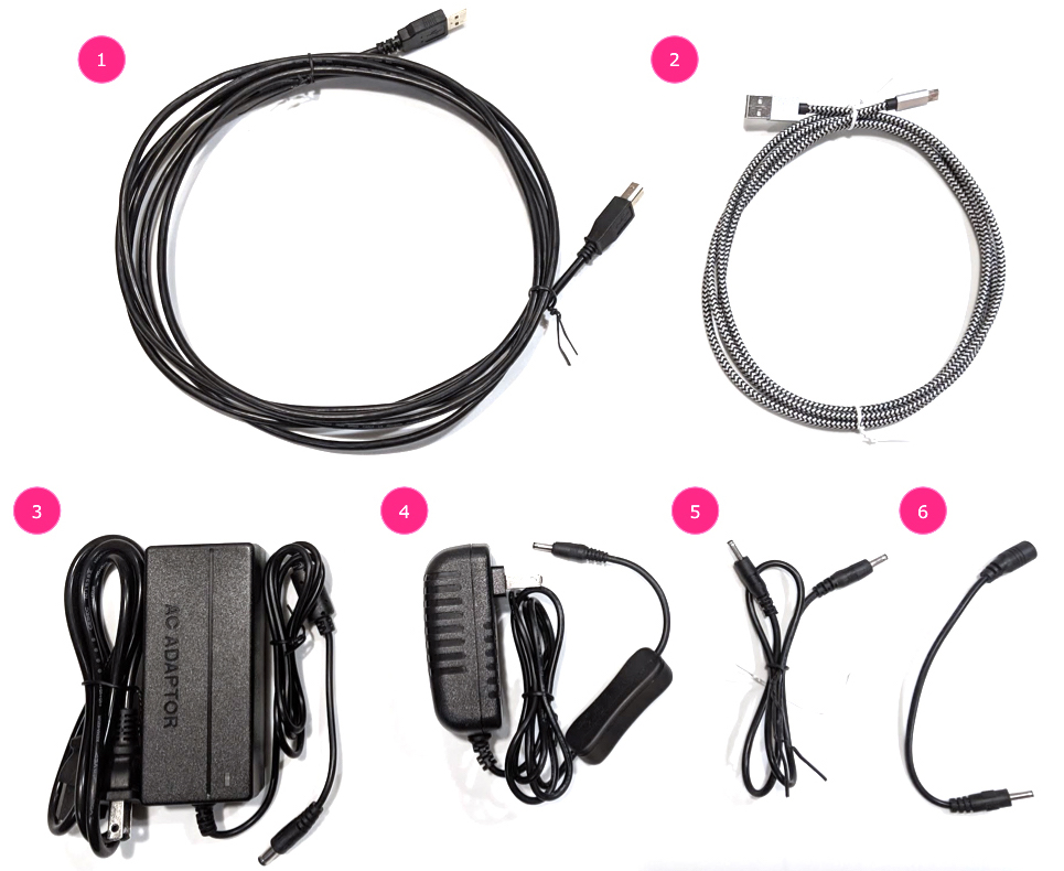
Şekil 1. Sensör birleştirme testi için gereken bileşenler
USB A - B kablosu
USB A - C kablosu (test telefonu için)
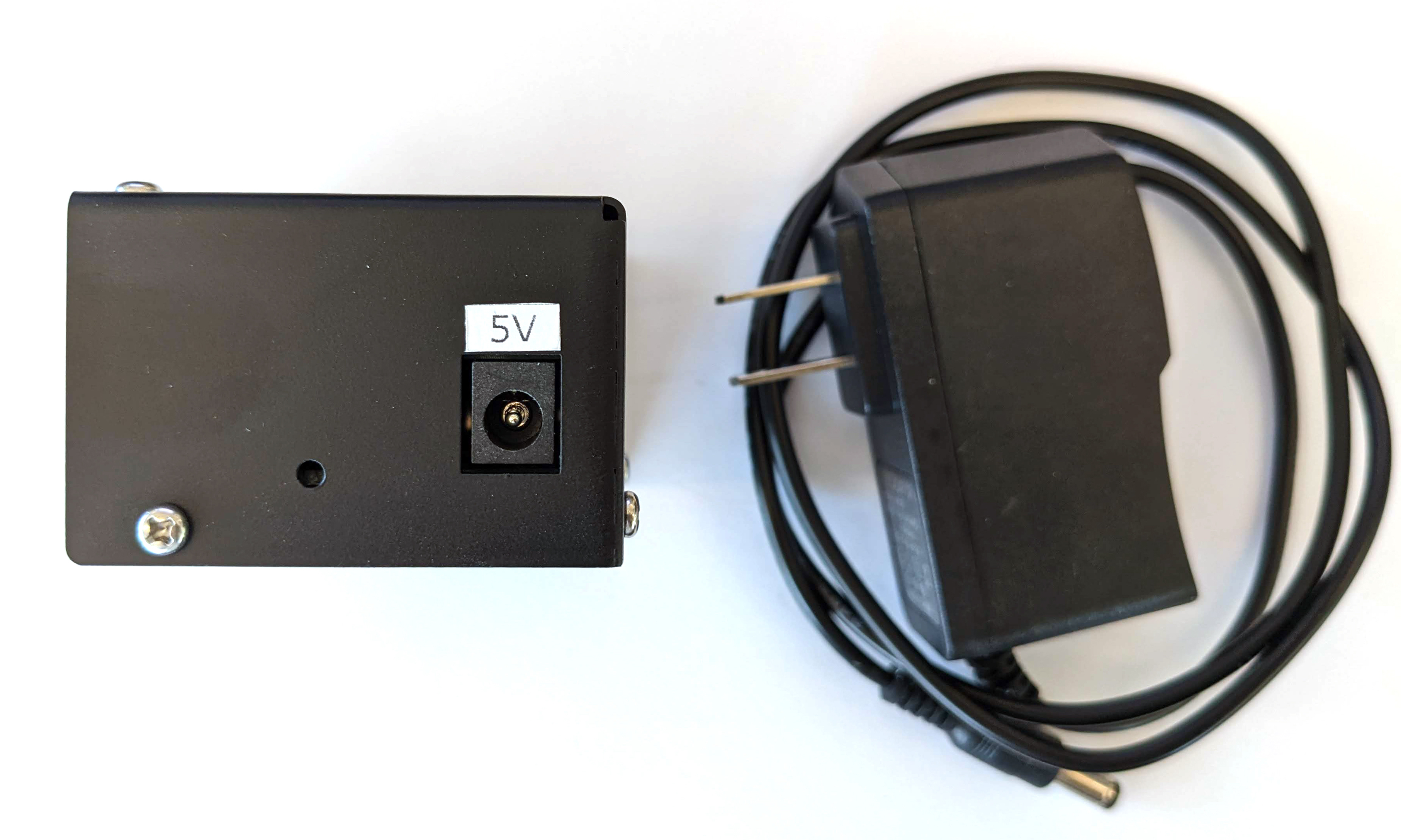
12 V 2 A güç kablosu (servo kontrol kutusu için)
12 V güç kablosu (aydınlatma için, anahtarla)
5 V erkek-erkek bağlantı kablosu (aydınlatma için)
5 V erkek-dişi dönüştürücü kablo (aydınlatma için)
1. adım: Işıkları bağlayın
Işıkları bağlamak için:
Şekil 2'de gösterildiği gibi, iki ışığı alt uçlarından erkek-erkek kabloyla bağlayın. Kablo, işlemin yapılmasına engel olmamak için kutunun alt kısmına sabitlenmelidir.
Işığın, ışık kablosunun çıkış deliğine daha yakın olan ucunu dönüşüm kablosuna bağlayın
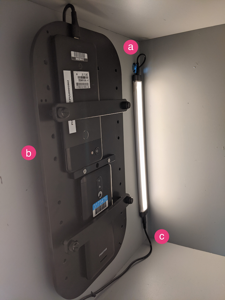
Şekil 2. Işıkları birbirine ve bir lambayı dönüşüm kablosuna bağlama
Işık kablosu çıkış deliği
USB kablosu çıkış deliği
5 V erkek-erkek dönüştürücü kablo
Dönüşüm kablosunun bağlı olmayan ucunu kutudan çıkan yuvarlak delikten geçirin, ardından aydınlatma için güç kablosuna bağlayın.
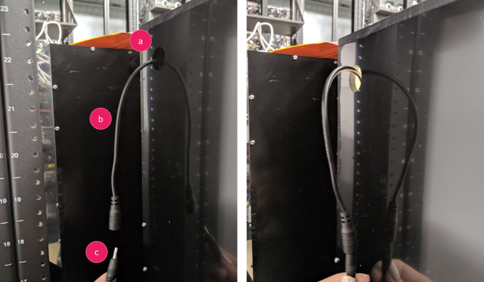
Şekil 3. Kutudan çıkan ve güç kablosuna bağlanan aydınlatma dönüşüm kablosu
Çıkış deliği
Dönüşüm kablosu
Güç kablosu
2. adım: Servoyu takın
Servoyu takmak için:
Servo konnektörünü servo kontrolüne takın. Sıranın tersine çevrilmesi motora zarar verebileceğinden, konnektörü etiketlendiği gibi ilgili renklere (S = Sarı, K = Kırmızı, S = Siyah) göre yerleştirdiğinizden emin olun. Kablo çok kısaysa
servo uzatma kablosu kullanın.
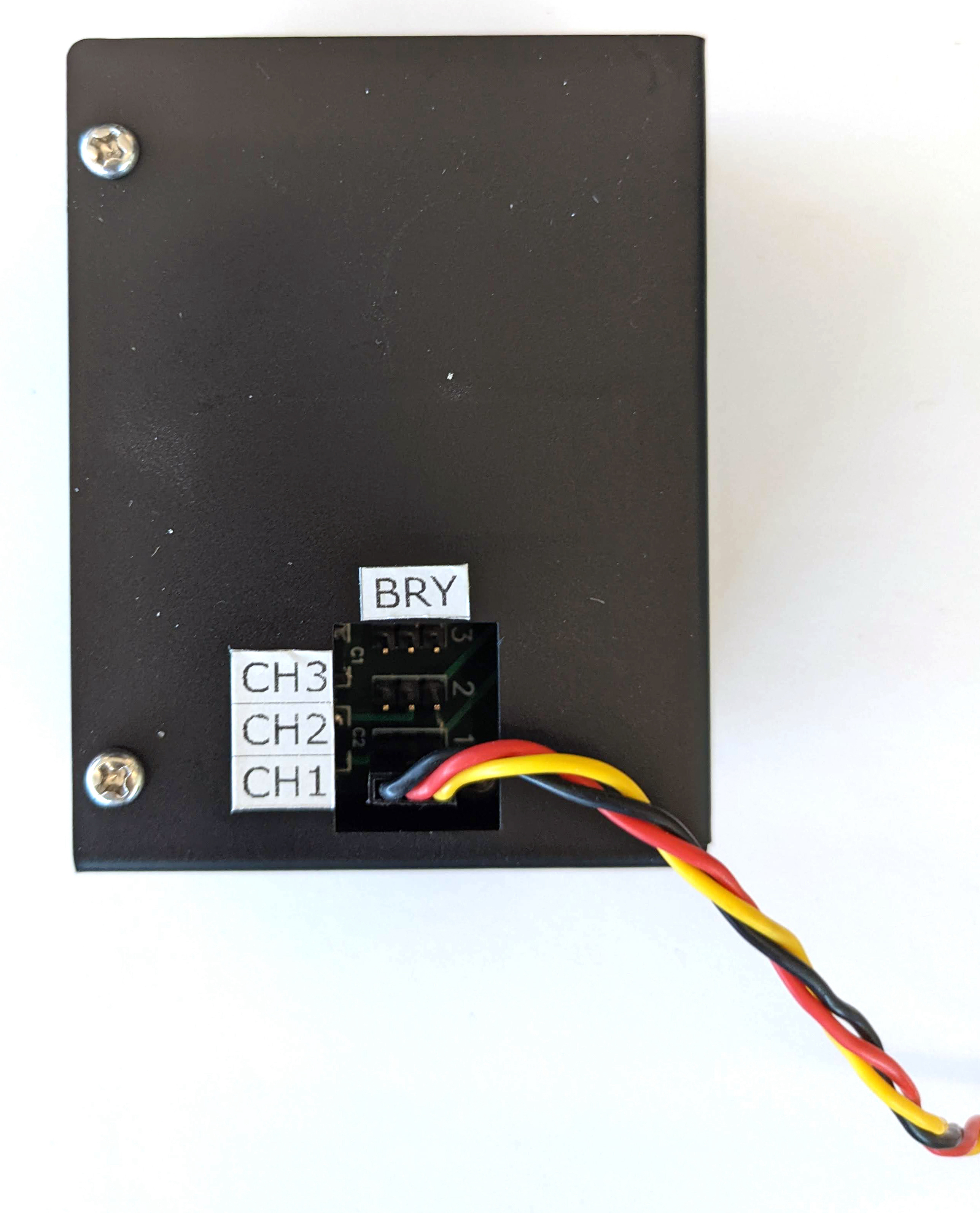
Şekil 4. Servo kontrol kutusuna bağlanan servo
Servo kontrolünü güç kablosuyla bağlayın (aydınlatma ve servo kontrolünün bağımsız, özel güç kaynakları vardır).
Şekil 5. Servo kontrolünü özel güç kablosuna bağlama
Servo kontrol kutusunu ana makineye (testi çalıştıran makineye) bağlamak için USB A - B kablosunu kullanın.
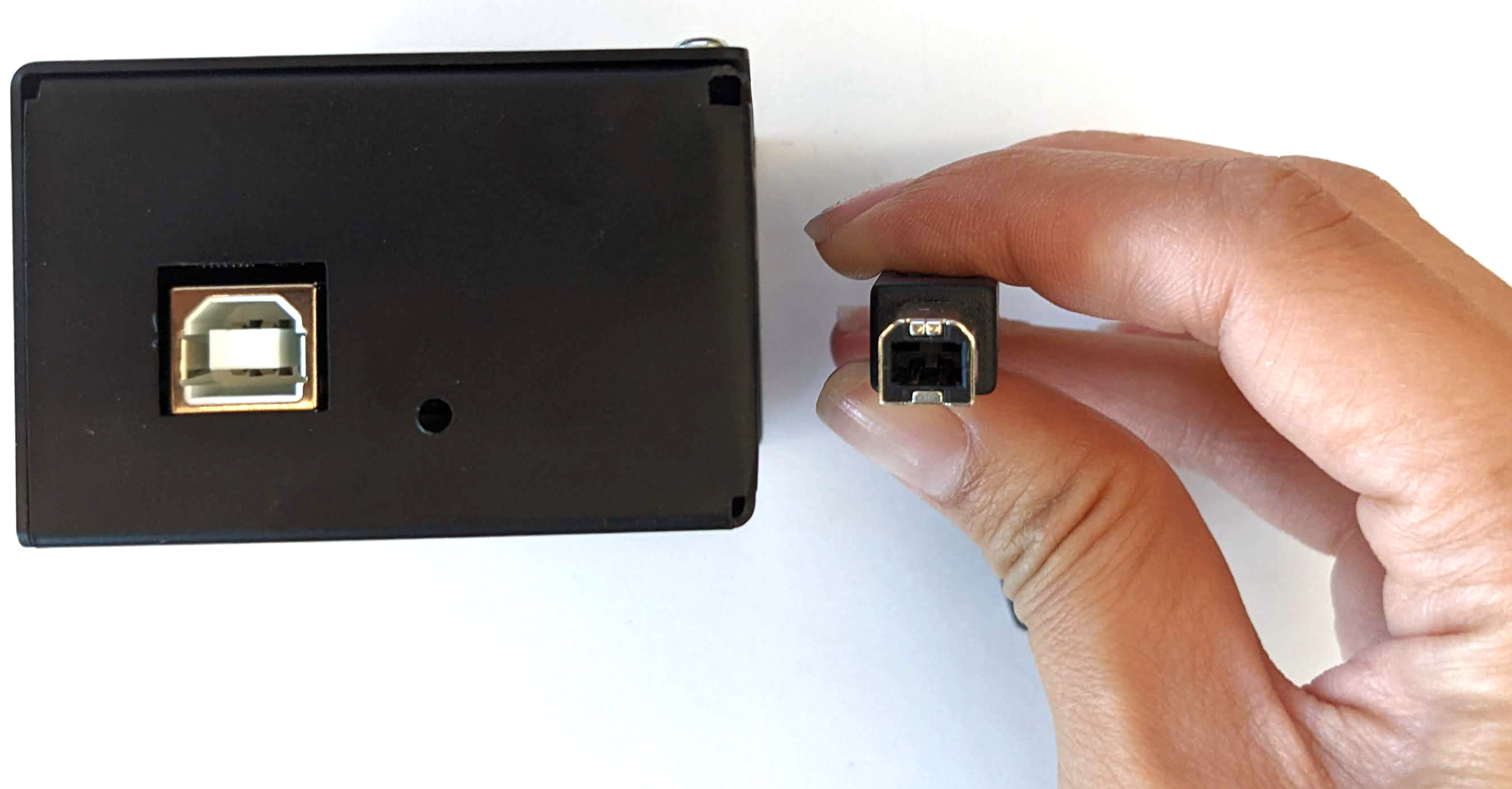
Şekil 6. Servo kontrol kutusunu ana makineye bağlama
3. Adım: Telefonu bağlayın
Telefonu aparata yerleştirin ve kelepçeleyin. Naylon vidayı sağa çevirerek sıkın. 
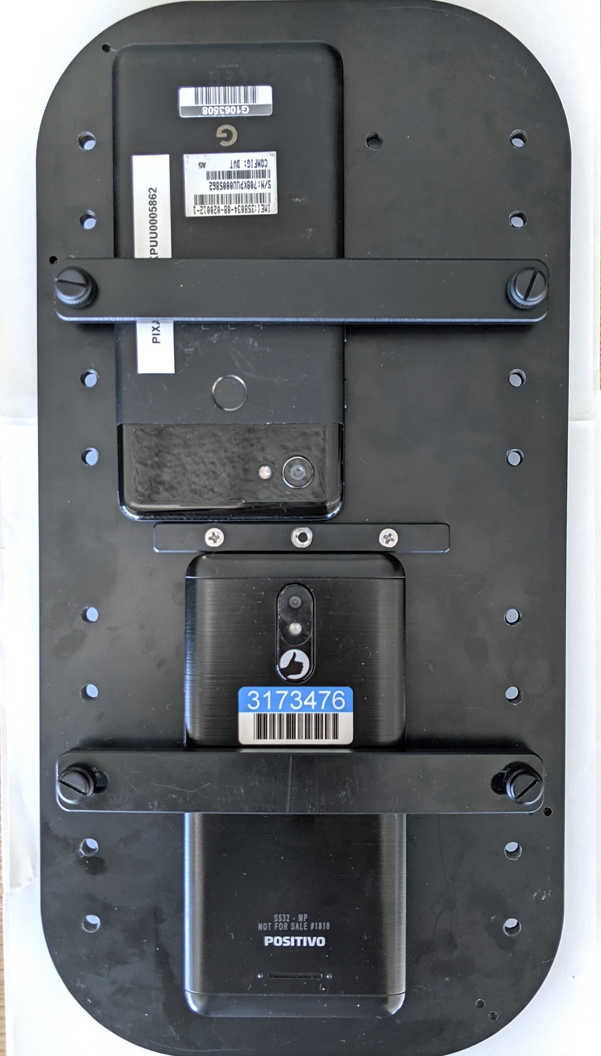
Şekil 7. Telefonu aparata yerleştirme ve sabitleme
Telefonlar, USB kablolarının telefon montajının kenarına, kameraların ise montajın merkezine yakın bir yere gelecek şekilde yerleştirilmelidir.
Telefon USB kablosunu, sabitleme plakasına sabitlemek ve çıkış deliğinden kutunun dışına çıkarmak için bir kablo bağı kullanın. Kablosun diğer ucunu testi çalıştıran ana makineye takın.
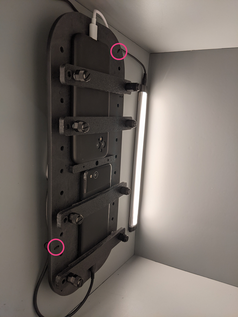
Şekil 8. Telefon USB kablosu, sabitleyiciye fermuar bağlarıyla tutturulmuş
4. Adım: Test komut dosyasını çalıştırın
Test komut dosyası için ana Python yürütülebilir dosyası:
Aşağıdakileri kullanarak komutu gerçek döndürücü adresini belirtecek şekilde değiştirebilirsiniz:
rot_rig=VID:PID:CH
Tedarikçi firma kimliğini (VID) ve ürün kimliğini (PID) belirlemek için Linux lsusb komutunu kullanın.
Varsayılan olarak VID ve PID, "1" kanalıyla 04d8 ve fc73 olarak ayarlanır.
Birden fazla çalıştırma, farklı biçimler
Farklı biçimlerde birden fazla çalıştırma yapmak için farklı bir komut dosyası kullanabilirsiniz (ancak sonuçlar CtsVerifier.apk'e yüklenmez). Örnek test komut dosyası:
USB bağlantı noktası üzerinden motoru kontrol etmeyle ilgili izin sorunlarını çözmek için:
Operatör kullanıcı adını dialout grubuna eklemek için:
sudo adduser USERNAME dialout
Operatörün oturumunu kapatın.
Operatöre giriş yapın.
Bu sayfadaki içerik ve kod örnekleri, İçerik Lisansı sayfasında açıklanan lisanslara tabidir. Java ve OpenJDK, Oracle ve/veya satış ortaklarının tescilli ticari markasıdır.
Son güncelleme tarihi: 2025-07-30 UTC.
[[["Anlaması kolay","easyToUnderstand","thumb-up"],["Sorunumu çözdü","solvedMyProblem","thumb-up"],["Diğer","otherUp","thumb-up"]],[["İhtiyacım olan bilgiler yok","missingTheInformationINeed","thumb-down"],["Çok karmaşık / çok fazla adım var","tooComplicatedTooManySteps","thumb-down"],["Güncel değil","outOfDate","thumb-down"],["Çeviri sorunu","translationIssue","thumb-down"],["Örnek veya kod sorunu","samplesCodeIssue","thumb-down"],["Diğer","otherDown","thumb-down"]],["Son güncelleme tarihi: 2025-07-30 UTC."],[],[],null,["# Test sensor fusion\n\nThe sensor fusion test measures timestamp accuracy of sensors for\nAndroid devices, specifically camera image sensors and gyroscopes. This\npage provides step-by-step directions on\nhow to setup the Sensor Fusion test and Sensor Fusion Box for the first\ntime.\n\nVideo tutorial\n--------------\n\n\nThis is a video tuturial on how to set up the sensor fusion box. \n\nRequired tools\n--------------\n\n\nBefore getting started, ensure you have the following components:\n**Figure 1.** Components required for the sensor fusion test\n\n1. USB A to B cable\n2. USB A to C cable (for test phone)\n3. 12V 2A power cord (for servo control box)\n4. 12V power cord (for lighting, with switch)\n5. 5V male-male connection cable (for lighting)\n6. 5V male-female conversion cable (for lighting)\n\nStep 1: Connect lights\n----------------------\n\n\nTo connect the lights:\n\n1. Use the male-male cable to connect the two lights on the bottom ends of the lights as shown in figure 2. Secure the cable to the bottom of the box to keep the cable from interfering with the operation.\n2. Connect the end of the light closer to the light cable exit hole to the conversion cable **Figure 2.** Connecting the lights to each other and one light to the conversion cable\n 1. Light cable exit hole\n 2. USB cable exit hole\n 3. 5V male-male conversion cable\n3. Thread the unconnected end of the conversion cable through the round hole that exits the box, then connect it to the power cable for lighting. **Figure 3.** Lighting conversion cable exiting the box and connecting to power cable\n 1. Exit hole\n 2. Conversion cable\n 3. Power cable\n\nStep 2: Attach servo\n--------------------\n\n\nTo attach the servo:\n\n1. Plug the servo connector into the servo control. Be sure to insert the connector oriented to the corresponding colors as labeled (Y = Yellow, R = Red, B = Black), as reversing the order could damage the motor. If the cord is too short, use a [servo extension cable](https://www.adafruit.com/product/972). **Figure 4.** Servo connecting to the servo control box\n2. Connect the servo control with its power cord (the lighting and servo control have independent, dedicated power supplies). **Figure 5.** Connecting the servo control to its dedicated power cord\n3. Use the USB A to B cable to connect the servo control box to the host (machine that is running the test). **Figure 6.** Connecting the servo control box to the host machine\n\nStep 3: Attach phone\n--------------------\n\n1. Set the phone on the fixture and clamp it down. Tighten by turning the nylon screw right. \n **Figure 7.** Placing and clamping the phone on the fixture\n\n Phones should be placed in a manner where the USB cords are located at\n the periphery of the phone mount and the cameras are near the center of\n the mount.\n2. Use a zip tie to hold the phone USB cord to the fixture plate and lead it outside the box through the exit hole. Plug the other end of the cord to the host running the test. **Figure 8.** Phone USB cord held to fixture with zip ties\n\nStep 4: Run test script\n-----------------------\n\n\nThe main python executable for the test script is: \n\n python tools/run_all_tests.py device=ID camera=0 scenes=sensor_fusion rot_rig=default\n \nYou can modify the command to specify the actual rotator address by using: \n\n```scdoc\nrot_rig=VID:PID:CH\n \n```\n\n- To determine the Vendor ID (VID) and Product ID (PID), use the Linux command `lsusb`.\n- By default, the VID and PID are set to `04d8` and `fc73` with channel \"1\".\n\n### Multiple runs, different formats\n\nTo perform multiple runs with different formats, you can use a\ndifferent script (however, the results will not be uploaded to\n`CtsVerifier.apk`). Sample test script: \n\n python tools/run_sensor_fusion_box.py device=FA7831A00278 camera=0 rotator=default img_size=640,360 fps=30 test_length=7\n\n### Permission issues\n\nTo resolve permission issues related to controlling the motor through the\nUSB port:\n\n1. Add the operator username to the `dialout` group using: \n\n sudo adduser \u003cvar translate=\"no\"\u003eUSERNAME\u003c/var\u003e dialout\n \n2. Log out the operator.\n3. Log in the operator."]]