Mulai 27 Maret 2025, sebaiknya gunakan android-latest-release, bukan aosp-main, untuk mem-build dan berkontribusi pada AOSP. Untuk mengetahui informasi selengkapnya, lihat Perubahan pada AOSP.
Tetap teratur dengan koleksi
Simpan dan kategorikan konten berdasarkan preferensi Anda.
Pengujian penggabungan sensor mengukur akurasi stempel waktu sensor untuk
perangkat Android, khususnya sensor gambar kamera dan giroskop. Halaman
ini memberikan petunjuk langkah demi langkah tentang
cara menyiapkan pengujian Sensor Fusion dan Sensor Fusion Box untuk pertama
kalinya.
Video tutorial
Ini adalah tutorial video tentang cara menyiapkan kotak penggabungan sensor.
Alat yang diperlukan
Sebelum memulai, pastikan Anda memiliki komponen berikut:
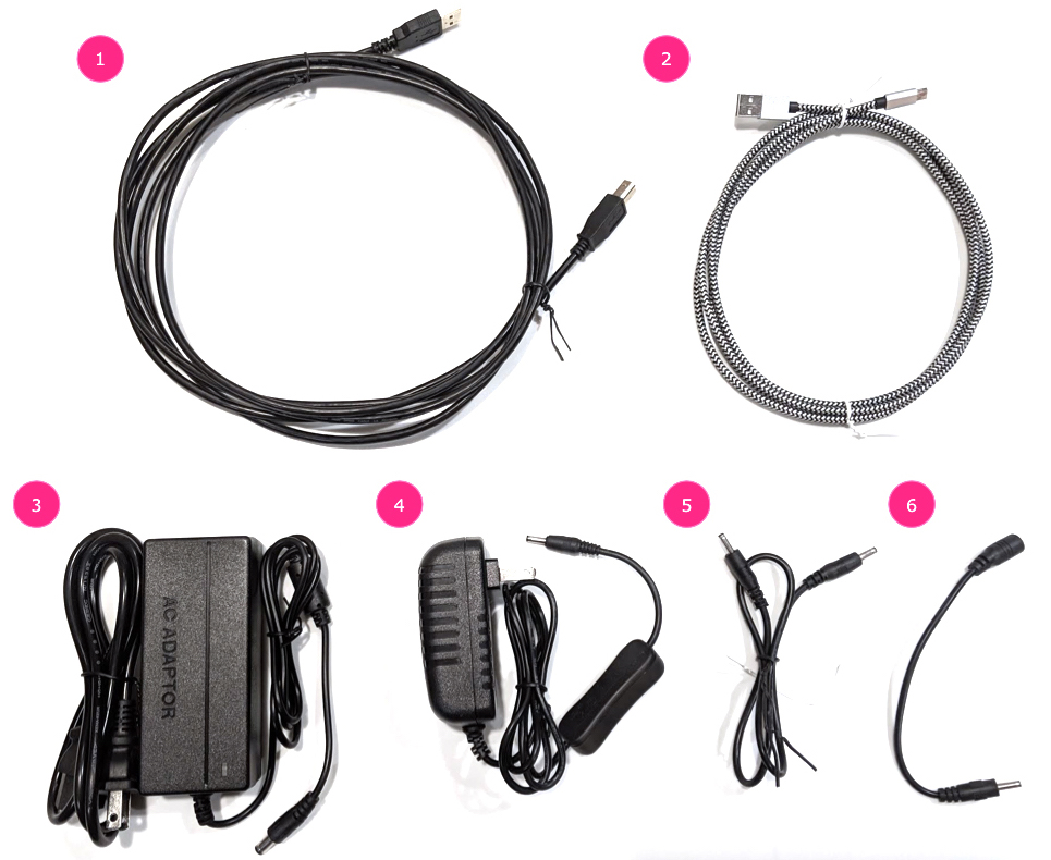
Gambar 1. Komponen yang diperlukan untuk pengujian
penggabungan sensor
Kabel USB A ke B
Kabel USB A ke C (untuk ponsel pengujian)
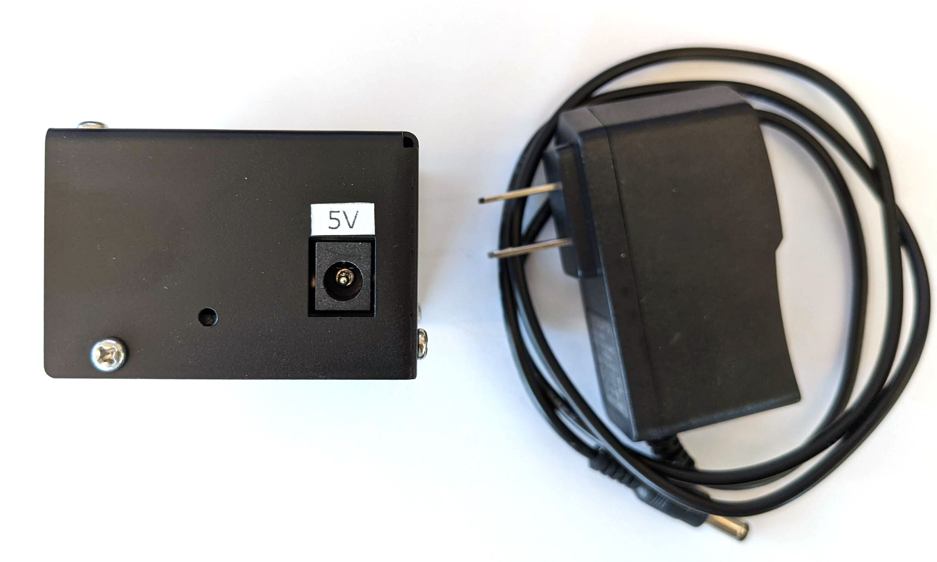
Kabel daya 12 V 2 A (untuk kotak kontrol servo)
Kabel daya 12 V (untuk pencahayaan, dengan tombol)
Kabel koneksi male-male 5 V (untuk pencahayaan)
Kabel konversi male-female 5 V (untuk pencahayaan)
Langkah 1: Hubungkan lampu
Untuk menghubungkan lampu:
Gunakan kabel male-male untuk menghubungkan kedua lampu di ujung bawah lampu seperti yang ditunjukkan pada gambar 2. Kencangkan kabel ke bagian bawah
kotak agar kabel tidak mengganggu operasi.
Hubungkan ujung lampu lebih dekat ke lubang keluar kabel lampu ke
kabel konversi
Gambar 2. Menghubungkan lampu satu sama lain dan
satu lampu ke kabel konversi
Lubang keluar kabel lampu
Lubang keluar kabel USB
Kabel konversi male-male 5 V
Masukkan ujung kabel konversi yang tidak terhubung melalui lubang
bulat yang keluar dari kotak, lalu hubungkan ke kabel
daya untuk pencahayaan.
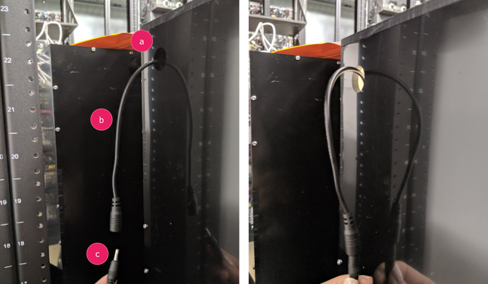
Gambar 3. Kabel konversi pencahayaan yang keluar dari kotak
dan terhubung ke kabel daya
Lubang keluar
Kabel konversi
Kabel daya
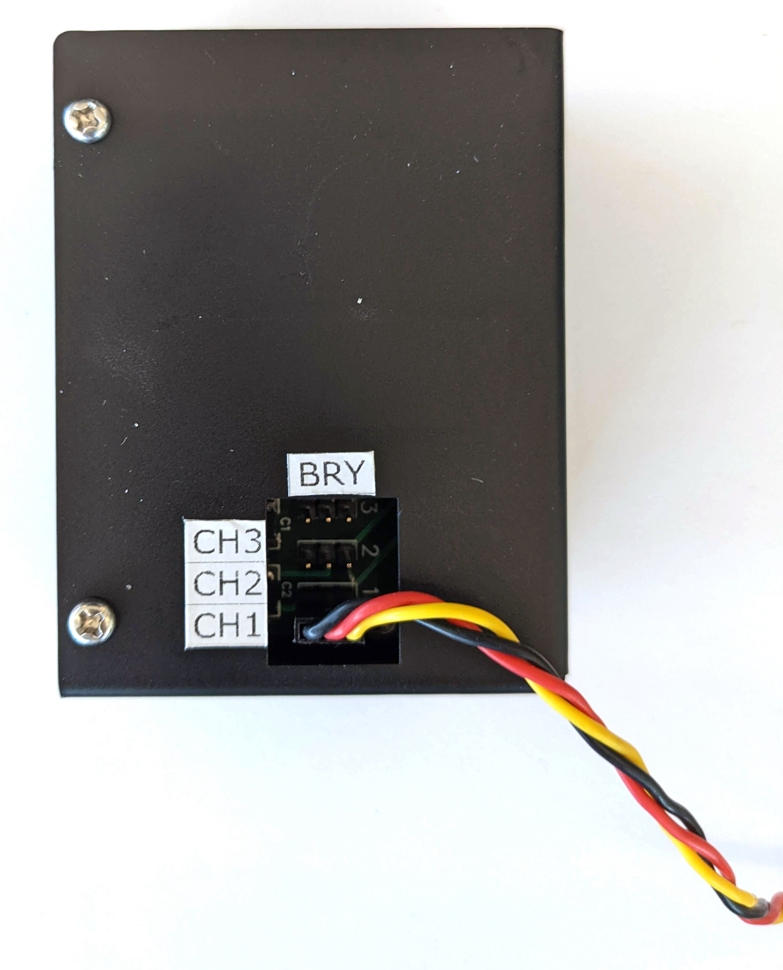
Langkah 2: Pasang servo
Untuk memasang servo:
Colokkan konektor servo ke kontrol servo. Pastikan untuk memasukkan
konektor yang berorientasi pada warna yang sesuai seperti yang diberi label (Y =
Kuning, R = Merah, B = Hitam), karena membalik urutan dapat merusak
motor. Jika kabel terlalu pendek, gunakan
kabel ekstensi servo.
Gambar 4. Servo yang terhubung ke kotak kontrol
servo
Hubungkan kontrol servo dengan kabel daya (kontrol pencahayaan dan
servo memiliki catu daya khusus yang independen).
Gambar 5. Menghubungkan kontrol servo ke
kabel daya khusus
Gunakan kabel USB A ke B untuk menghubungkan kotak kontrol servo ke
host (mesin yang menjalankan pengujian).
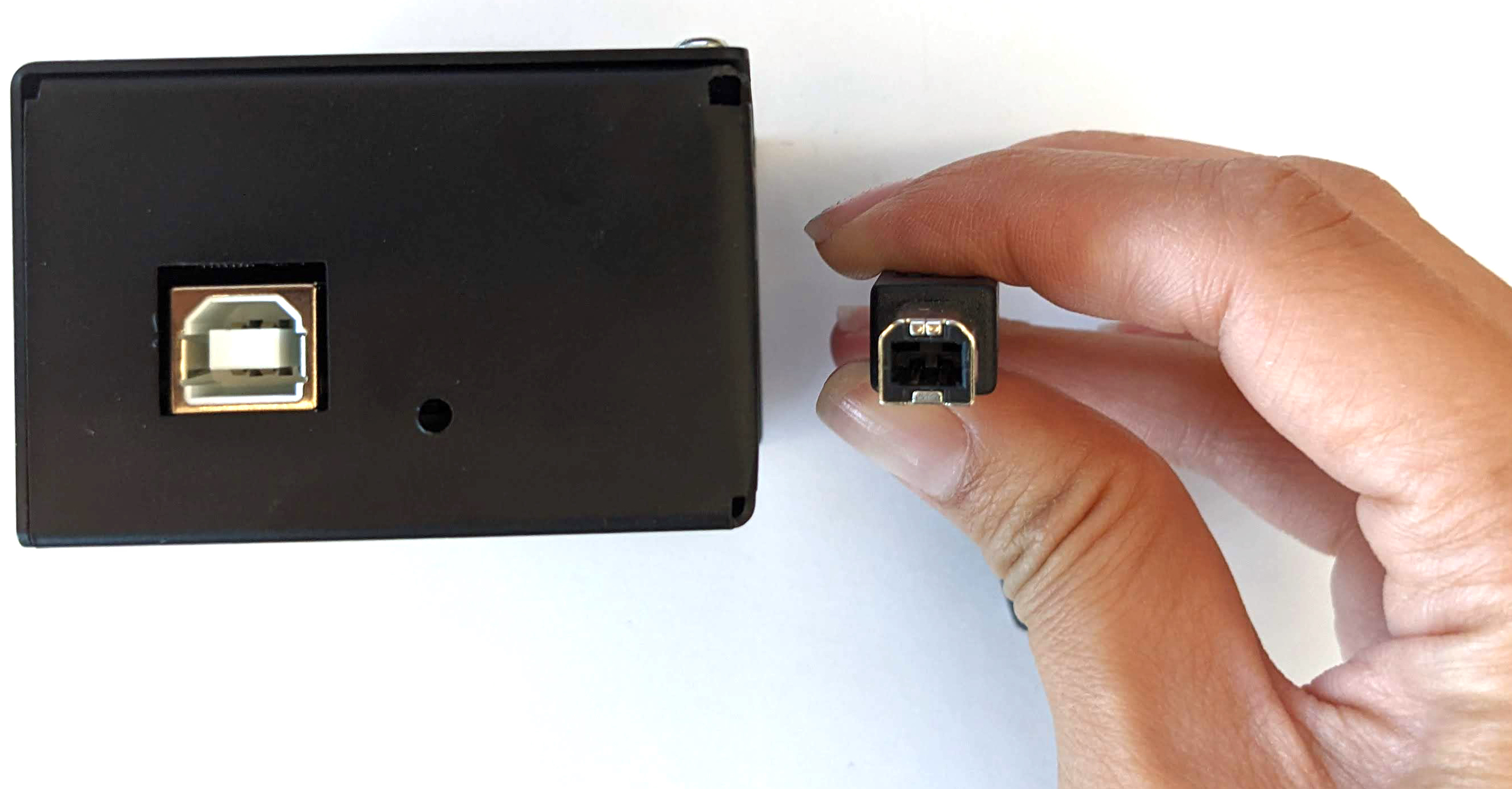
Gambar 6. Menghubungkan kotak kontrol servo ke
mesin host
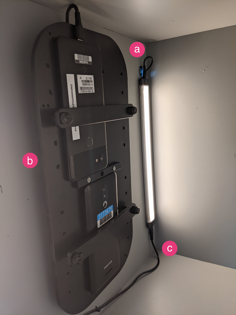
Langkah 3: Pasang ponsel
Letakkan ponsel di dudukan dan kencangkan. Kencangkan dengan memutar
sekrup nilon ke kanan. 
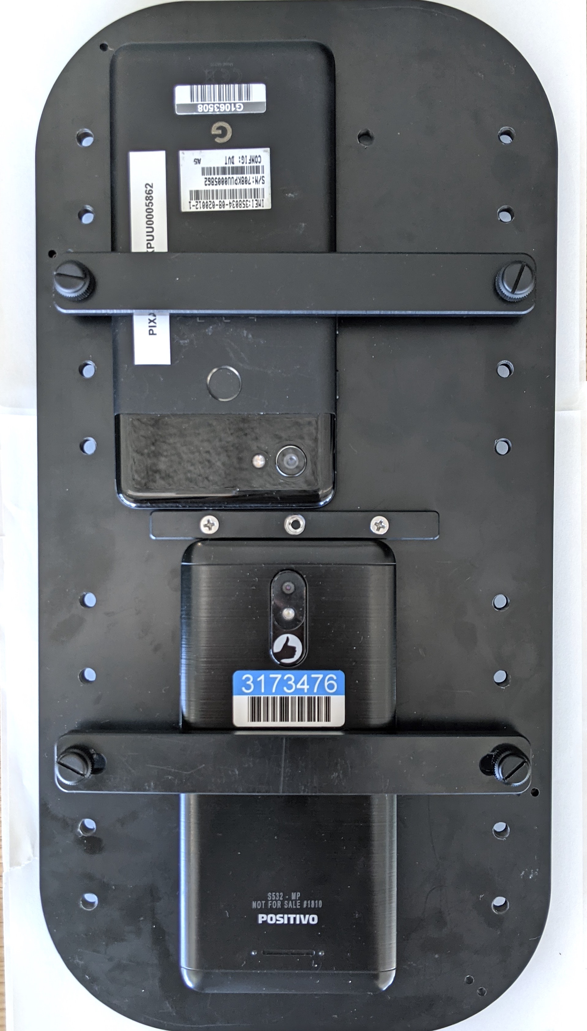
Gambar 7. Menempatkan dan menjepit ponsel di
perlengkapan
Ponsel harus ditempatkan sedemikian rupa sehingga kabel USB berada di
pinggiran dudukan ponsel dan kamera berada di dekat pusat
dudukan.
Gunakan kabel ties untuk menahan kabel USB ponsel ke pelat perlengkapan dan
mengarahkannya ke luar kotak melalui lubang keluar. Colokkan ujung kabel lainnya ke host yang menjalankan pengujian.
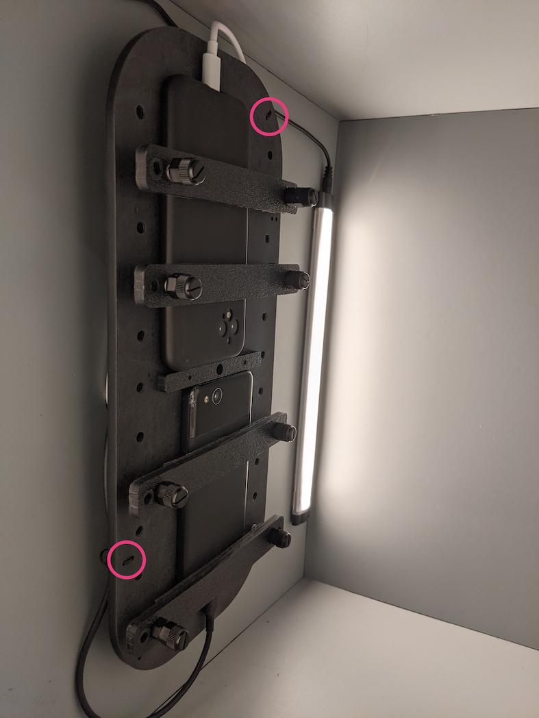
Gambar 8. Kabel USB ponsel diikat ke perlengkapan dengan
kabel ties
Langkah 4: Jalankan skrip pengujian
File python utama yang dapat dieksekusi untuk skrip pengujian adalah:
Anda dapat mengubah perintah untuk menentukan alamat rotator yang sebenarnya menggunakan:
rot_rig=VID:PID:CH
Untuk menentukan ID Vendor (VID) dan ID Produk (PID), gunakan perintah Linux
lsusb.
Secara default, VID dan PID ditetapkan
ke 04d8 dan fc73 dengan saluran "1".
Beberapa operasi, format berbeda
Untuk melakukan beberapa operasi dengan format yang berbeda, Anda dapat menggunakan skrip yang berbeda (tetapi, hasilnya tidak akan diupload ke CtsVerifier.apk). Contoh skrip pengujian:
Untuk mengatasi masalah izin yang terkait dengan pengontrolan motor melalui
port USB:
Tambahkan nama pengguna operator ke grup dialout menggunakan:
sudo adduser USERNAME dialout
Logout operator.
Login operator.
Konten dan contoh kode di halaman ini tunduk kepada lisensi yang dijelaskan dalam Lisensi Konten. Java dan OpenJDK adalah merek dagang atau merek dagang terdaftar dari Oracle dan/atau afiliasinya.
Terakhir diperbarui pada 2025-07-30 UTC.
[[["Mudah dipahami","easyToUnderstand","thumb-up"],["Memecahkan masalah saya","solvedMyProblem","thumb-up"],["Lainnya","otherUp","thumb-up"]],[["Informasi yang saya butuhkan tidak ada","missingTheInformationINeed","thumb-down"],["Terlalu rumit/langkahnya terlalu banyak","tooComplicatedTooManySteps","thumb-down"],["Sudah usang","outOfDate","thumb-down"],["Masalah terjemahan","translationIssue","thumb-down"],["Masalah kode / contoh","samplesCodeIssue","thumb-down"],["Lainnya","otherDown","thumb-down"]],["Terakhir diperbarui pada 2025-07-30 UTC."],[],[],null,["# Test sensor fusion\n\nThe sensor fusion test measures timestamp accuracy of sensors for\nAndroid devices, specifically camera image sensors and gyroscopes. This\npage provides step-by-step directions on\nhow to setup the Sensor Fusion test and Sensor Fusion Box for the first\ntime.\n\nVideo tutorial\n--------------\n\n\nThis is a video tuturial on how to set up the sensor fusion box. \n\nRequired tools\n--------------\n\n\nBefore getting started, ensure you have the following components:\n**Figure 1.** Components required for the sensor fusion test\n\n1. USB A to B cable\n2. USB A to C cable (for test phone)\n3. 12V 2A power cord (for servo control box)\n4. 12V power cord (for lighting, with switch)\n5. 5V male-male connection cable (for lighting)\n6. 5V male-female conversion cable (for lighting)\n\nStep 1: Connect lights\n----------------------\n\n\nTo connect the lights:\n\n1. Use the male-male cable to connect the two lights on the bottom ends of the lights as shown in figure 2. Secure the cable to the bottom of the box to keep the cable from interfering with the operation.\n2. Connect the end of the light closer to the light cable exit hole to the conversion cable **Figure 2.** Connecting the lights to each other and one light to the conversion cable\n 1. Light cable exit hole\n 2. USB cable exit hole\n 3. 5V male-male conversion cable\n3. Thread the unconnected end of the conversion cable through the round hole that exits the box, then connect it to the power cable for lighting. **Figure 3.** Lighting conversion cable exiting the box and connecting to power cable\n 1. Exit hole\n 2. Conversion cable\n 3. Power cable\n\nStep 2: Attach servo\n--------------------\n\n\nTo attach the servo:\n\n1. Plug the servo connector into the servo control. Be sure to insert the connector oriented to the corresponding colors as labeled (Y = Yellow, R = Red, B = Black), as reversing the order could damage the motor. If the cord is too short, use a [servo extension cable](https://www.adafruit.com/product/972). **Figure 4.** Servo connecting to the servo control box\n2. Connect the servo control with its power cord (the lighting and servo control have independent, dedicated power supplies). **Figure 5.** Connecting the servo control to its dedicated power cord\n3. Use the USB A to B cable to connect the servo control box to the host (machine that is running the test). **Figure 6.** Connecting the servo control box to the host machine\n\nStep 3: Attach phone\n--------------------\n\n1. Set the phone on the fixture and clamp it down. Tighten by turning the nylon screw right. \n **Figure 7.** Placing and clamping the phone on the fixture\n\n Phones should be placed in a manner where the USB cords are located at\n the periphery of the phone mount and the cameras are near the center of\n the mount.\n2. Use a zip tie to hold the phone USB cord to the fixture plate and lead it outside the box through the exit hole. Plug the other end of the cord to the host running the test. **Figure 8.** Phone USB cord held to fixture with zip ties\n\nStep 4: Run test script\n-----------------------\n\n\nThe main python executable for the test script is: \n\n python tools/run_all_tests.py device=ID camera=0 scenes=sensor_fusion rot_rig=default\n \nYou can modify the command to specify the actual rotator address by using: \n\n```scdoc\nrot_rig=VID:PID:CH\n \n```\n\n- To determine the Vendor ID (VID) and Product ID (PID), use the Linux command `lsusb`.\n- By default, the VID and PID are set to `04d8` and `fc73` with channel \"1\".\n\n### Multiple runs, different formats\n\nTo perform multiple runs with different formats, you can use a\ndifferent script (however, the results will not be uploaded to\n`CtsVerifier.apk`). Sample test script: \n\n python tools/run_sensor_fusion_box.py device=FA7831A00278 camera=0 rotator=default img_size=640,360 fps=30 test_length=7\n\n### Permission issues\n\nTo resolve permission issues related to controlling the motor through the\nUSB port:\n\n1. Add the operator username to the `dialout` group using: \n\n sudo adduser \u003cvar translate=\"no\"\u003eUSERNAME\u003c/var\u003e dialout\n \n2. Log out the operator.\n3. Log in the operator."]]