다양한 CTS 인증 도구 테스트에는 오디오 루프백 시스템이 있어야 생성된 신호를 측정할 수 있습니다. 즉, 오디오 신호는 출력에서 입력으로 루프백됩니다. 루프백 시스템이 작동하려면 생성된 신호가 안정적으로 캡처될 만큼 충분히 커야 합니다. 이 보정을 쉽게 하려면 루프백 CTS 테스트에서 오디오 루프백 보정 패널에 액세스하여 테스트를 시작하기 전에 적절한 신호 진폭을 설정하세요.
오디오 루프백 보정 패널 사용
오디오 루프백 보정 패널은 오디오 루프백을 사용하는 CTS 인증 도구 테스트에서 Calibrate Audio를 사용하여 호출합니다(다음 그림 참고).
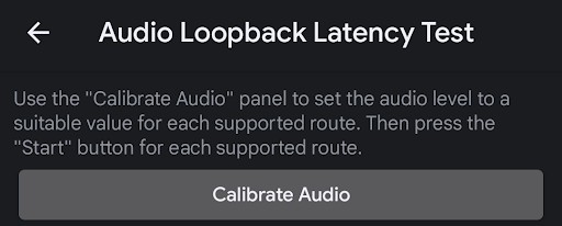
그림 1. 오디오 루프백 지연 시간 테스트
다음 그림은 보정 패널을 보여줍니다.
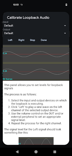
그림 2. 루프백 오디오 보정 패널
보정할 루프백 주변기기 선택
보정할 루프백 주변기기를 선택하는 가장 쉬운 방법은 보정할 오디오 주변기기를 연결하거나 루프백이 내부 스피커와 마이크 사이에 있는 경우 기기를 연결하지 않고 Input 및 Output 선택을 Default로 두는 것입니다.
왼쪽 채널 보정
Left 버튼을 눌러 주변기기의 왼쪽 채널에서 신호를 재생합니다. DUT의 볼륨 키를 사용하여 볼륨을 조정합니다. 주변기기가 자체 입력 수준 컨트롤이 있는 외부 USB 인터페이스라면 디스플레이에 신호가 적절하게 표시될 때까지 볼륨을 적절히 조정합니다.
신호가 너무 낮음
다음 그림은 테스트에 사용하기에 진폭이 충분하지 않은 왼쪽 채널의 신호를 보여줍니다. 신호를 높은 수준으로 조정합니다.
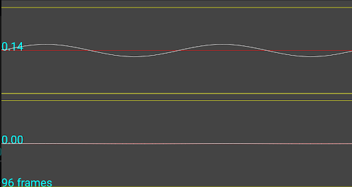
그림 3. 신호가 너무 낮음
신호가 너무 높음
다음 그림은 캡처 기기에서 클리핑되어 테스트에 적절한 신호가 아닌 진폭이 너무 큰 왼쪽 채널의 신호를 보여줍니다. 신호를 낮은 수준으로 조정합니다.
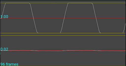
그림 4. 신호가 너무 높음
적절한 신호
다음 그림은 테스트하기에 최적인 왼쪽 채널의 신호를 보여주는 예입니다.
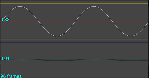
그림 5. 적절한 신호
오른쪽 채널 보정
Right 버튼을 눌러 주변기기의 오른쪽 채널에서 신호를 재생합니다. 왼쪽 채널 보정에 설명된 프로세스를 따라 테스트에 최적인 수준을 설정합니다.
1채널 캡처 기기 보정
채널이 하나뿐인 캡처 주변기기(내부 마이크 또는 아날로그 헤드셋 잭에 연결된 루프백 플러그)의 경우 재생되는 채널과 관계없이 두 채널에서 모두 동일한 신호가 디스플레이에 표시됩니다. 이는 예상된 동작이므로 신호 수준을 왼쪽 채널 보정에 설명된 대로 설정해야 합니다.
명시적 입력 및 출력 주변기기 선택
보정할 루프백 주변기기 선택에서 설명한 대로 특정 루프백 주변기기를 보정하는 가장 쉬운 방법은 주변기기를 연결하고(또는 스피커 또는 마이크 경로에 대해 아무것도 연결하지 않음) 입력 및 출력 메뉴에서 Default를 선택하는 것입니다. 하지만 디버깅에 도움이 되도록 메뉴에서 사용 가능한 기기를 선택해도 됩니다. 이러한 목록은 현재 사용할 수 있는 모든 주변기기 입력 및 출력 경로의 목록으로 채워져 있습니다.
이 페이지에 나와 있는 콘텐츠와 코드 샘플에는 콘텐츠 라이선스에서 설명하는 라이선스가 적용됩니다. 자바 및 OpenJDK는 Oracle 및 Oracle 계열사의 상표 또는 등록 상표입니다.
최종 업데이트: 2025-05-09(UTC)
[[["이해하기 쉬움","easyToUnderstand","thumb-up"],["문제가 해결됨","solvedMyProblem","thumb-up"],["기타","otherUp","thumb-up"]],[["필요한 정보가 없음","missingTheInformationINeed","thumb-down"],["너무 복잡함/단계 수가 너무 많음","tooComplicatedTooManySteps","thumb-down"],["오래됨","outOfDate","thumb-down"],["번역 문제","translationIssue","thumb-down"],["샘플/코드 문제","samplesCodeIssue","thumb-down"],["기타","otherDown","thumb-down"]],["최종 업데이트: 2025-05-09(UTC)"],[],[],null,["# Audio Loopback Calibration panel\n\n\u003cbr /\u003e\n\nA number of CTS Verifier tests require an audio loopback system so that\ngenerated signals can be measured, that is, the audio signal *loops back* from\nthe output to the input. For this to work, the generated signal must be loud\nenough to be reliably captured. To make this *calibration* easier, the Audio\nLoopback Calibration Panel is accessible from any loopback CTS test to set an\nappropriate signal amplitude before starting the test.\n\nUse the Audio Loopback Calibration panel\n----------------------------------------\n\nThe Audio Loopback Calibration panel is invoked using **Calibrate Audio**\nin any of the CTS Verifier tests that use audio loopback, as shown in the\nfollowing figure.\n\n**Figure 1.** Audio loopback latency test.\n\nThe following figure shows the calibration panel.\n\n**Figure 2.** Calibrate loopback audio panel.\n\n### Select the loopback peripheral to calibrate\n\nThe easiest way to select the loopback peripheral to calibrate is to connect the\naudio peripheral to be calibrated, or to not connect any device if the loopback\nis between the internal speaker and microphone, and to leave the **Input** and\n**Output** selection set to **Default**.\n\n### Calibrate the left channel\n\nPress the **Left** button to play a signal on the left channel of the\nperipheral. Adjust the volume by using the volume keys on the DUT. If the\nperipheral is an external USB interface with its own input level controls,\nadjust them as appropriate until you see an appropriate signal on the display.\n\n#### Signal too low\n\nThe following figure shows a signal on the left channel with insufficient\namplitude to be used for testing. Adjust the signal to a higher level.\n\n**Figure 3.** Signal too low.\n\n#### Signal too high\n\nThe following figure shows a signal on the left channel with too much amplitude\nsuch that it is *clipping* at the capture device and is not an appropriate\nsignal for testing. Adjust the signal to a lower level.\n\n**Figure 4.** Signal too high.\n\n#### Signal just right\n\nThe following figure example shows a signal on the left channel which is optimal\nfor testing.\n| **Note:** In some cases, a signal this high can't be produced. In such cases, set a signal level that is as high as possible without clipping.\n\n**Figure 5.** Signal just right.\n\n### Calibrate the right channel\n\nPress the **Right** button to play a signal on the right channel of the\nperipheral. Follow the process described in [Calibrate the left channel](#calibrate-left-channel)\nto set the optimal level for testing.\n\n### Calibrate a 1-channel capture device\n\nIn the case of a capture peripheral with only 1 channel (that is, the internal\nmic or a loopback plug connected to the analog headset jack), the display shows\nthe same signal on both channels irrespective of which channel is playing. This\nbehavior is as expected and the signal level must be set as described in\n[Calibrate the left channel](#calibrate-left-channel).\n\n### Explicit Input and Output peripheral selection\n\nAs stated in [Select the loopback peripheral to calibrate](#select-loopback-peripheral),\nthe simplest way to calibrate a given loopback peripheral is to connect it\n(or leave none connected for the Speaker or Microphone route) and select\n**Default** in the Input and Output menus. However, to help with debugging,\nyou can choose any available devices from the menus. These lists are populated\nwith a list of all the currently available peripheral input and output routes."]]