
CTS Verifier audio tests require the following audio peripherals to be connected:
- 3.5 mm analog headset
- Audio loopback plug
- USB-to-analog headset adapter
- USB audio interface
- Multichannel USB audio peripherals
- MIDI peripherals
3.5 mm analog headset
An Android-compatible analog headset with a 4-conductor, 3.5 mm phone plug is required for tests that verify analog headset plug detection, audio signal playback, and inline media transport buttons (Volume Up, Volume Down, and Headset Hook or Media Transport). These headsets are widely available and often identified with the term Built For Android, though many standard 4-conductor analog headsets are compatible.
An example headset and plug are shown in the following figures:
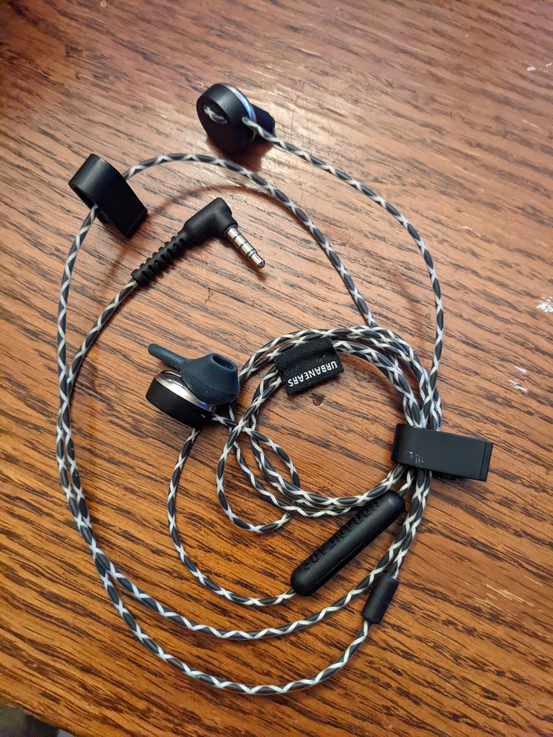
Figure 1. Example Android-compatible analog headset.
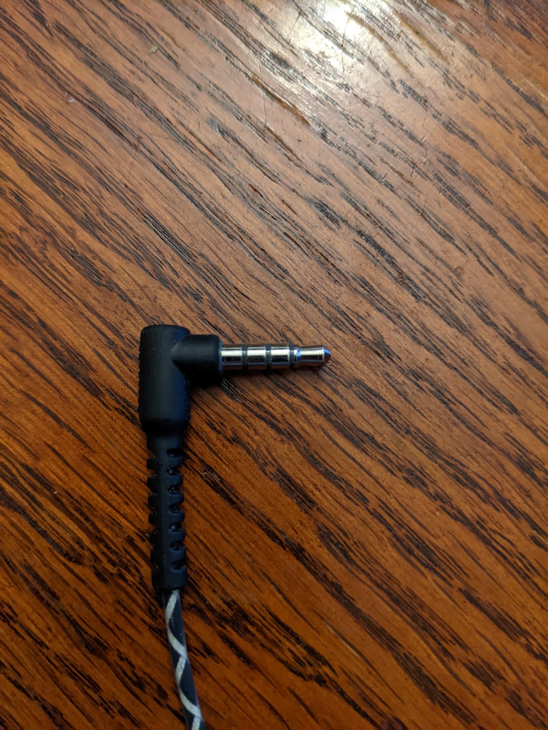
Figure 2. Example 4-conductor, 3.5 mm analog phone plug.
Audio loopback plug
The audio loopback plug contains electronics that route the signal coming from the 3.5 mm analog headphone jack back to the input in the headphone jack. This imitates an analog headset, so that's how it appears to the DUT, albeit with a perfect loopback route from the output to the input.
For a circuit diagram and a link to a manufacturer, see the Audio loopback plug.
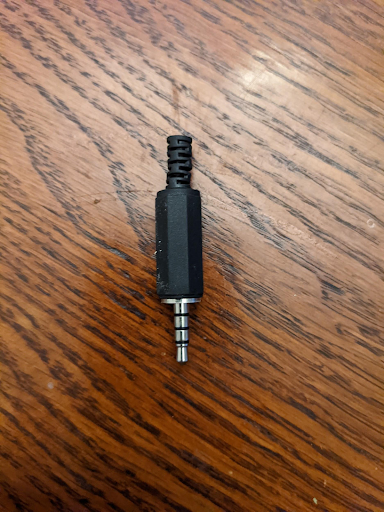
Figure 3. Audio loopback plug.
Calibrate for an analog loopback
The volume level of the output on the 3.5 mm headset jack is controlled by volume buttons, typically located on the side of the DUT. To set an appropriate level for the 3.5 mm headset jack and the audio loopback plug, do the following:
- Start the CTS Verifier test in question.
- Insert the analog loopback plug in the 3.5 mm analog headset jack.
- Start the Audio Loopback Calibration panel and start the playback process.
- Use the volume buttons on the DUT to adjust the level as specified in Audio Loopback Calibration panel.
USB-to-analog headset adapter
A USB-to-analog headset adapter converts the USB digital audio signal to a signal that is compatible with a standard analog headset jack. The adapter is typically connected to analog headphones or an analog headset. In this sense it's equivalent to the 3.5 mm analog headset jack found on some DUTs. However, its data route in the system is different and must be tested separately.
As with the 3.5 mm analog headset jack, an Audio loopback plug must be connected to the analog jack on the adapter for any tests requiring loopback. Further, the USB-to-analog headset adapter won't cause a USB connection to the DUT until an analog device (or the audio loopback adapter) is connected.
Some USB adapters won't work with CTS Verifier. For a list of tested adapters, see the USB audio adapter recommendation.
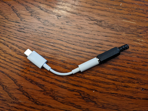
Figure 4. Audio loopback plug connected to USB-to-analog headset adapter.
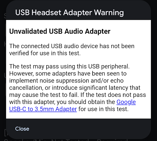
Figure 5. USB headset adapter warning.
The connected peripheral might be sufficient to pass a test. However, some adapters implement noise suppression or echo cancellation, or introduce additional latency (30 to 40 ms) that can cause the test to fail. If the test doesn't pass with that adapter, use the Google USB-C Digital to 3.5 mm adapter.
Calibrate for a USB-to-analog headset loopback
The volume level of the output on the USB audio port is controlled by volume buttons, typically located on the side of the DUT. To set an appropriate level for the 3.5 mm headset jack and audio loopback plug, do the following:
- Start the CTS Verifier test.
- Insert the USB-to-analog headset adapter and audio loopback plug into the DUT's USB port.
- Start the Audio calibration panel and start the playback process.
- Use the volume buttons on the DUT to adjust the level as specified in Audio calibration panel.
USB audio interface
A USB audio interface refers to an external device with a variety of inputs and outputs. These peripherals are generally intended for musical uses.
Due to the wide variety of commercially available interface devices, and their constantly changing availability, the CTS Verifier doesn't specify a specific make and model of the interface device. You must determine if a given USB interface works for the test.
Required additional hardware
This section lists the additional hardware required with the USB audio interface peripheral.
Patch cables
Use 1/4 inch to 1/4 inch male patch cables to connect the outputs to the inputs of the USB.
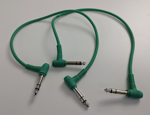
Figure 6. Patch cables.
USB peripheral cable
The USB peripheral cable (which typically comes with the peripheral) connects the USB audio peripheral to the host device.
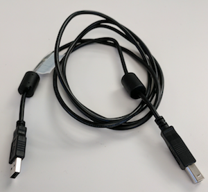
Figure 7. USB peripheral cable.
USB "On the Go" (OTG) adapter
A USB "On The Go" (OTG) adapter is required to physically connect the peripheral to the Android-powered device and indicate to the Android-powered device to assume the role of host.
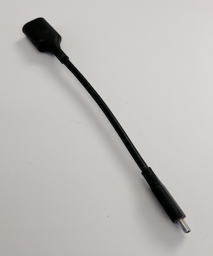
Figure 8. USB OTG adapter.
Configure for audio loopback
The following figures show the USB audio interface configurations:
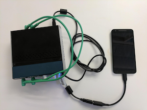
Figure 9. USB audio interface with loopback connected to an Android-powered device.
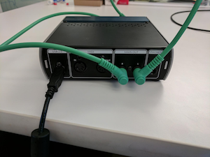
Figure 10. Connections on the back of the USB audio interface.
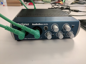
Figure 11. Connections on the front of the USB audio interface.
Calibrate for a USB audio interface
The volume level of the output on the USB audio port is controlled by the volume buttons (located on the side of the DUT) and controls on the USB audio interface itself. These controls generally include a level control for each input and a mix control that specifies the relative level of the signal from the input jacks and any signal coming from the USB audio input.
To set an appropriate level for the USB audio interface, do the following:
- Using the audio patch cables, connect the first input jack to the first output jack. One or both of these might be labeled either 1 or Left.
- Repeat for the second channel inputs or output, which might be labeled 2 or Right.
- Don't cross-connect the inputs and outputs by connecting the first input to the second output and the second output to the first input.
- Set both input levels on the USB audio interface to their lowest value.
- If present on the USB interface, set the mix control only to Playback, to prevent feedback.
- If the USB audio interface has a Monitor knob, set it to full volume to control the output volume.
- Start the CTS Verifier test.
- Start the Audio calibration panel and start the playback process.
- Use the volume buttons on the DUT to set the level to maximum level.
- Use the input level controls on the USB audio interface to adjust the level, as specified in Audio calibration panel to ensure the best signal-to-noise ratio.
Multichannel USB audio peripherals
Multichannel input and multichannel output tests verify 4-channel capture and 8-channel (Quad, 5.1, and 7.1) output masks using multi-channel USB audio hardware, loopback mixing or switching devices, and breakout cables.
4-channel input hardware and cables
Testing 4-channel input (audio data paths USB 4-channel input test) requires a 4-in/4-out USB audio interface and cables to loop each output channel back into its corresponding input channel:
Option 1: Zoom AMS-44 (4-in/4-out USB audio interface)
- Zoom AMS-44 (on Amazon) or Zoom AMS-44 (on AliExpress)
- Y-splitter cables: Two 3.5 mm stereo to dual 6.35 mm (1/4-inch) mono Y-splitter cables to split stereo outputs A and B into mono inputs 1–4.
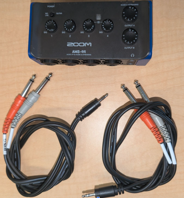
Figure 12. Zoom AMS-44 and Y-splitter cables.
Option 2: Focusrite Scarlett 4i4 (4th Gen, 4-in/4-out USB audio interface)
- Focusrite Scarlett 4i4 (on Sweetwater)
- Patch cables: Four 6.35 mm (1/4-inch) male-to-male cables
8-channel output hardware, mixers, and cables
Testing 8-channel output (audio data paths USB multichannel test) requires a 7.1-channel USB audio adapter and an audio mixer or switcher to route the eight discrete output channels back into a stereo input:
- 7.1-channel USB audio adapter:
- Vantec USB external 7.1-channel audio adapter (on Amazon), a class-compliant adapter that natively reports Quad, 5.1, and 7.1 output masks.
- Cables:
- Four 3.5 mm stereo auxiliary cables to connect the Vantec outputs to the mixer or switcher inputs.
- One 3.5 mm stereo to dual mono breakout Y-cable to route the mixed stereo output back to the Vantec stereo line-in input.
Stereo audio mixer or switcher (choose one):
Option 1 (Active mixer — recommended): 6-way stereo audio mixer
- 6-way stereo audio mixer (on eBay), 6-way stereo audio mixer (on AliExpress), or 6-way stereo audio mixer (on Amazon)
- DC power supply: Active mixers typically require a 5 V to 24 VDC (commonly 12 VDC, ≥ 500 mA) power supply with a standard 5.5 mm OD × 2.1 mm ID center-positive barrel connector (for example, on B&H, Amazon, or Electronix Express).
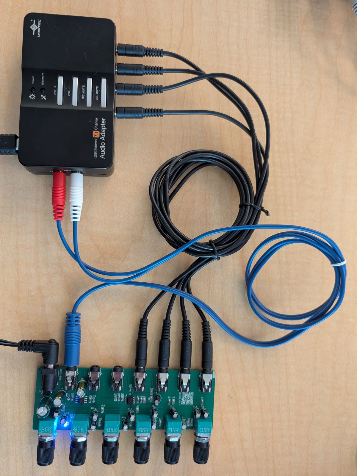
Figure 13. Active 6-way stereo mixer connection with Vantec 7.1 USB adapter.
Option 2 (Manual switcher): 4-channel audio switcher
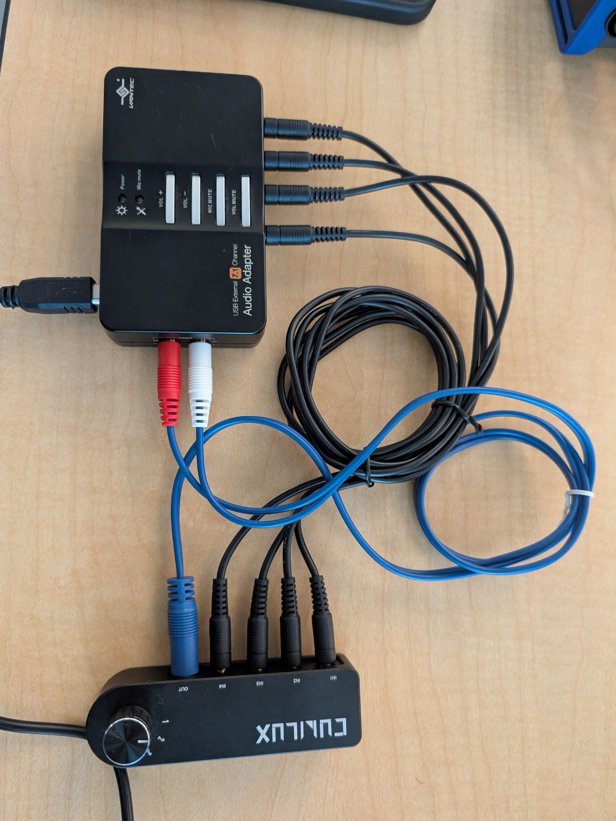
Figure 14. Manual 4-channel audio switcher connection with Vantec 7.1 USB adapter.
For detailed wiring diagrams and step-by-step calibration instructions, see Multichannel input and multichannel output tests.
MIDI peripherals
CTS Verifier MIDI tests verify that the Musical Instrument Digital Interface (MIDI) system functions as expected across USB MIDI, Bluetooth LE (BLE) MIDI, and virtual MIDI interfaces. Follow the peripheral requirements in the following sections for your specific Android version.
Required peripherals (Android 16 or higher)
Before running the CTS-V MIDI tests on Android 16 or higher, you must have these peripherals:
- A USB MIDI with associated loopback cables, such as Presonus Audio Box 96 with a standard 5-pin DIN MIDI cable
- A Bluetooth MIDI with associated cables, such as CME WIDI Jack with a 2.5 mm MIDI TRS cable
Examples of MIDI peripherals with associated loopback cables are shown in the following figures:
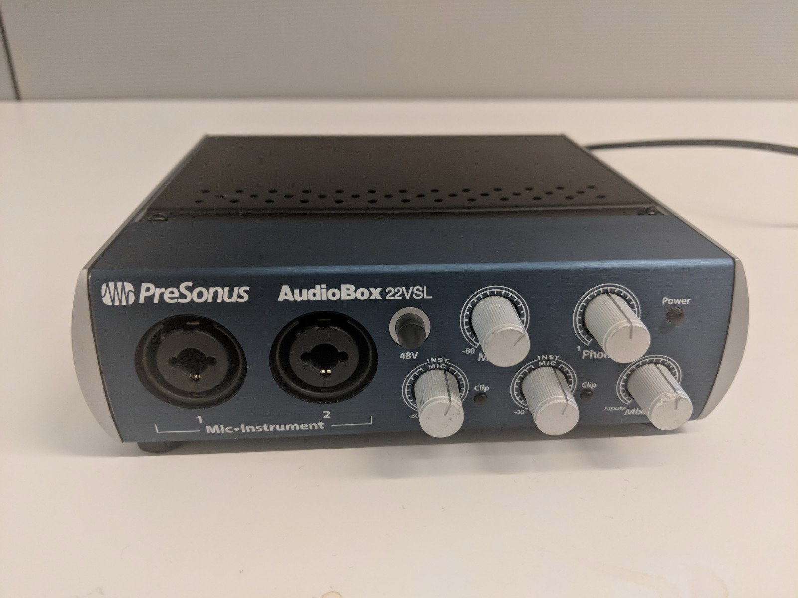
Figure 15. The front of a USB audio interface with MIDI I/O ports.
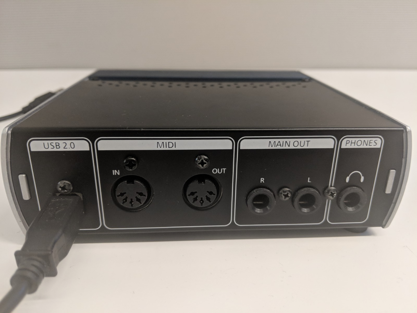
Figure 16. The back of a USB audio interface with MIDI I/O ports.
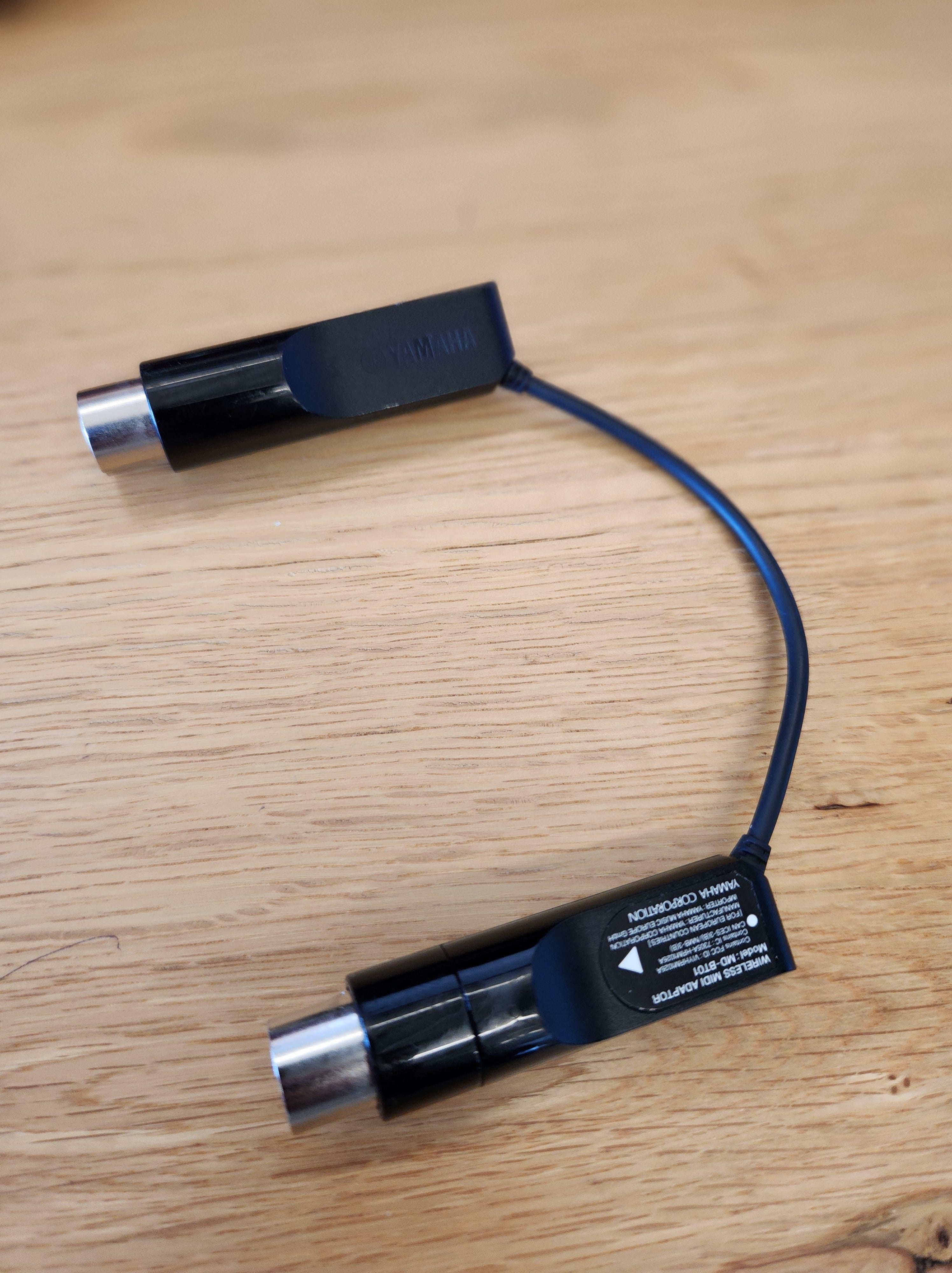
Figure 17. A standard 5-pin DIN MIDI cable.
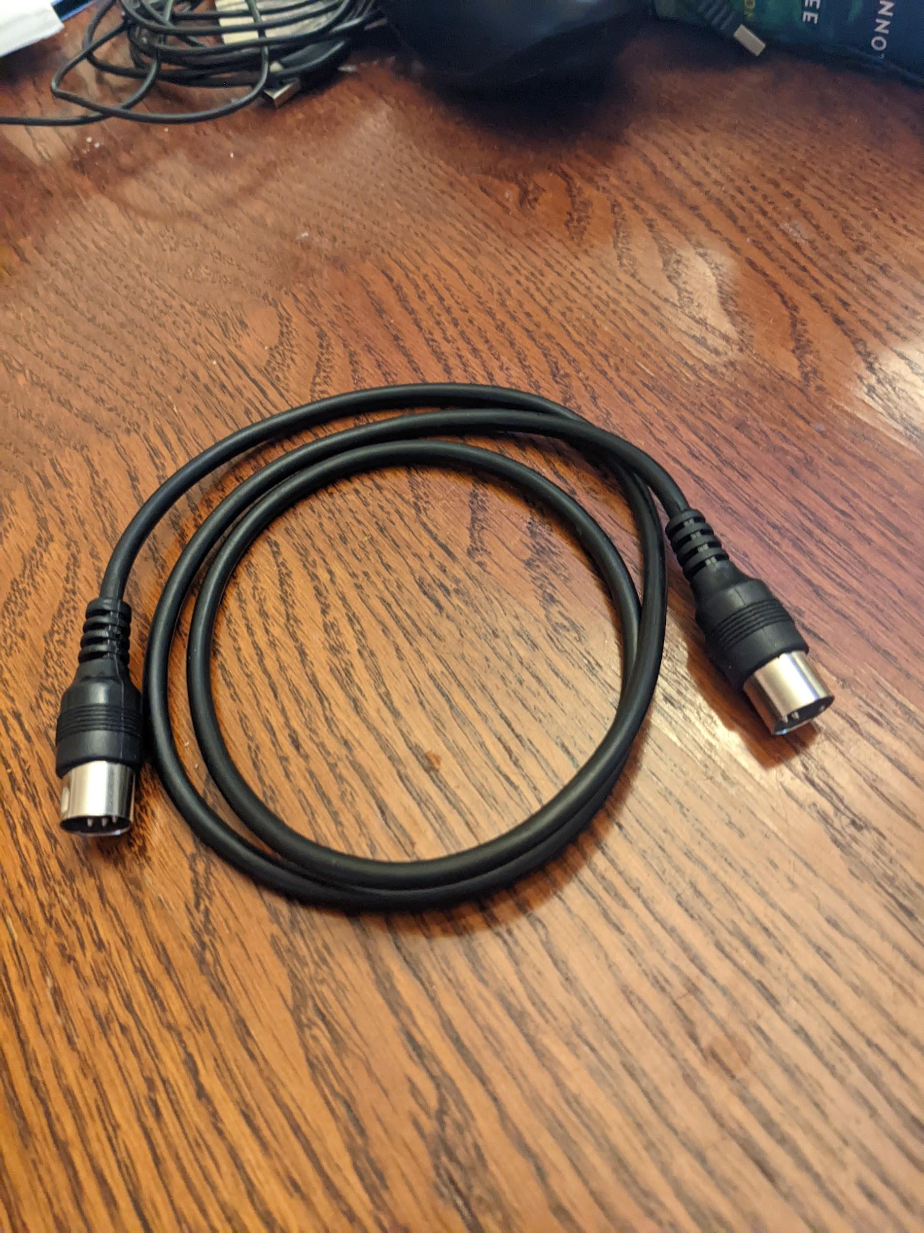
Figure 18. A Bluetooth MIDI interface with 5-pin DIN.
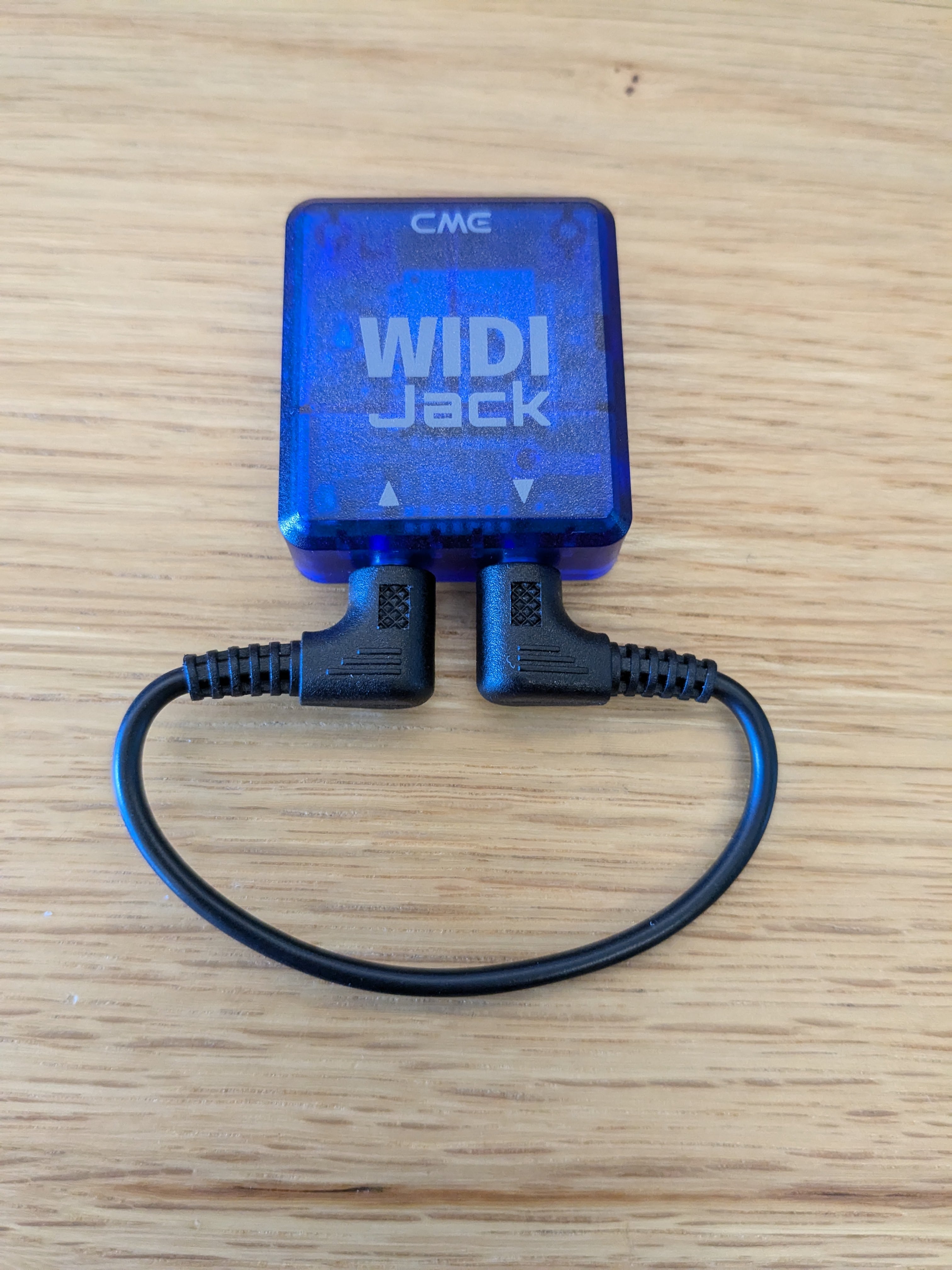
Figure 19. A Bluetooth MIDI interface with loopback.
Required peripherals (Android 15 or lower)
Before running the CTS-V MIDI tests on Android 15 or lower, you must have a MIDI peripheral with associated loopback cables. Examples of MIDI peripherals with associated loopback cables are shown in the following figures:
Figure 20. The front of a USB audio interface with MIDI I/O ports.
Figure 21. The back of a USB audio interface with MIDI I/O ports.
Figure 22. A standard 5-pin DIN MIDI cable.
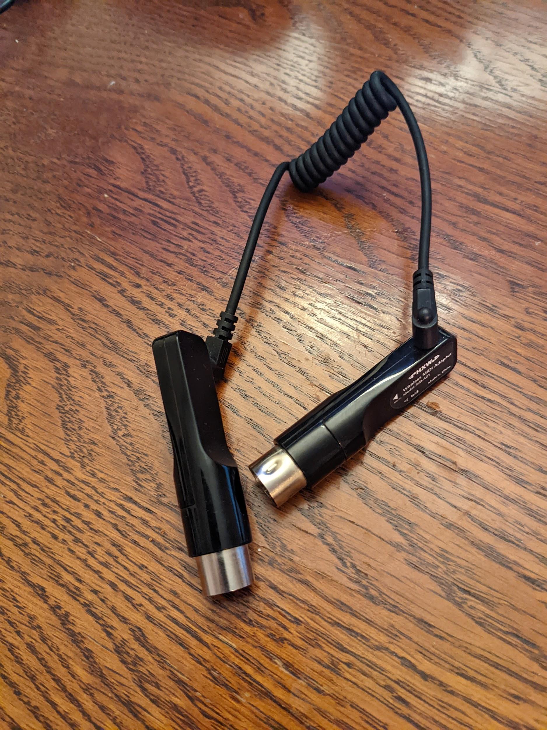
Figure 23. A Bluetooth MIDI interface, such as a Yamaha MD-BT01 or a Roland WM-1.