
이 페이지에서는 센서 퓨전 상자를 구매 또는 조립하는 방법에 관해 설명합니다. 센서 퓨전 상자는 CameraITS sensor_fusion 테스트 및 multi-camera 동기화 테스트에 사용되며 Android 기기의 센서, 특히 카메라 이미지 센서와 자이로스코프의 타임스탬프 정확도를 측정하는 데 일관된 테스트 환경을 제공합니다. 센서 퓨전 상자는 CAD(컴퓨터 보조 디자인) 도면에서 레이저로 잘라낸 플라스틱 상자 부품과 서보 제어 상자로 구성되어 있습니다.
센서 퓨전 상자는 구매하거나 직접 제작할 수 있습니다.
센서 퓨전 상자 구매하기
센서 퓨전 상자는 다음 공인 공급업체에서 구매하는 것이 좋습니다.
Byte Bridge Inc.
미국: 1502 Crocker Ave, Hayward, CA 94544-7037
중국: 22F #06-08, Hongwell International Plaza Tower A, 1600 West Zhongshan Road, Xuhui, Shanghai, 200235
www.bytebt.com
androidpartner@bytebt.com
미국: +1-510-373-8899
중국: +86-400-8866-490JFT CO LTD 捷富通科技有限公司(이전 명칭: MYWAY DESIGN)
중국: No. 40, Lane 22, Heai Road, Wujing Town, Minhang District, Shanghai, China
타이완: 4F., No. 163, Fu-Ying Road, XinZhuang District, New Taipei City 242, Taiwan
www.jftcoltd.com
service@jfttec.com or its.sales@jfttec.com
중국: +86-021-64909136
타이완: 886-2-29089060
센서 퓨전 상자 제작하기
이 섹션에서는 레이저로 잘라낸 ABS(아크릴로나이트릴 뷰타다이엔 스타이렌) 재질의 부품으로 센서 퓨전 상자를 조립하는 과정을 단계별로 설명합니다(그림 1 참고).
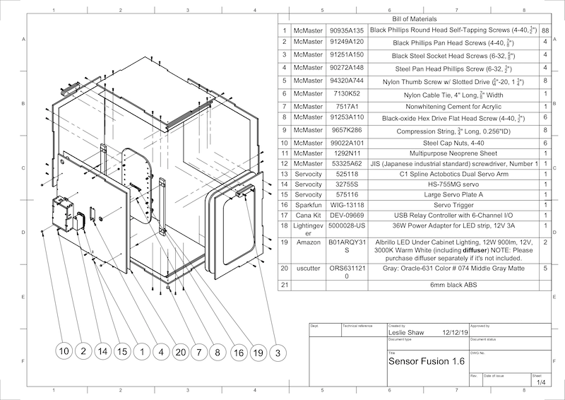
그림 1. 센서 퓨전 상자 부품의 기계 도면
필수 도구
시작하기 전에 센서 퓨전 상자의 기술 도면(센서 퓨전 상자 ZIP 파일에 포함됨)을 다운로드했는지 보고 다음 도구를 사용할 수 있는지 확인합니다.
- 십자드라이버
- JIS 헤드 스크루드라이버
- 6각 키
- 전기 드릴 세트
- X-ACTO 칼
- 테이프
1단계: 비닐 스티커 붙이기
레이저 커터로 ABS 부품을 만든 다음 플라스틱 상자에 비닐 스티커를 붙여 테스트 상자 내부의 색상을 적절하게 조정합니다.
그림 2에 나와 있는 것처럼 ABS의 매끄러운 면에 비닐을 붙입니다. 비닐을 붙이는 데 유용한 도움말은 wikiHow를 참고하세요.
exacto 커터칼로 비닐에서 필요한 구멍을 잘라냅니다.
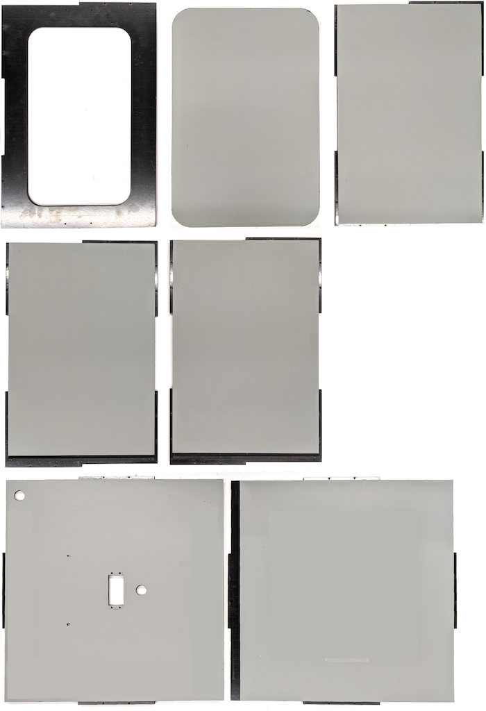
그림 2. 매끄러운 면에 비닐이 부착된 ABS 부품(상자 내부)아크릴 글루를 사용하여 원형 ABS 부품을 하단 패널의 네 모서리에 붙입니다.
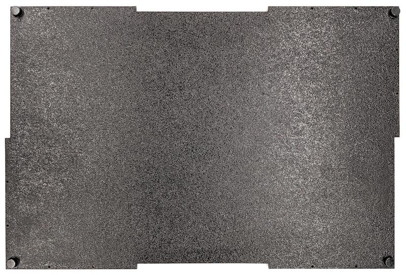
그림 3. 네 모서리에 원형 ABS 부품을 붙인 하단 패널
2단계: 스마트폰 마운트 준비 및 서보 마운트 부착
서보에 부착할 스마트폰 마운트를 준비하려면 다음 단계를 따릅니다.
1/4인치 20 드릴 비트로 스마트폰 고정대에 20개의 구멍을 뚫습니다.
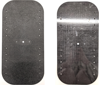
그림 4. 구멍이 뚫린 스마트폰 고정대잘라낸 ABS, 나일론 엄지 나사, 나일론 너트(필요한 경우 나사 높이를 조정하기 위함), C1 스플라인 액토보틱스 듀얼 서보 암, 4-40 나사 및 압축 스프링이 있는지 확인합니다.
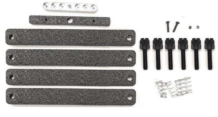
그림 5. 스마트폰 마운트 부품4-40 나사를 끼우고 서보 암을 스마트폰 마운트 뒷면에 조입니다(1.2N*m 또는 8.9in*lbf). 같은 나사와 4-40 캡 너트를 사용하여 스마트폰 마운트 앞면에 스마트폰 구분자인 잘라낸 ABS를 조입니다.
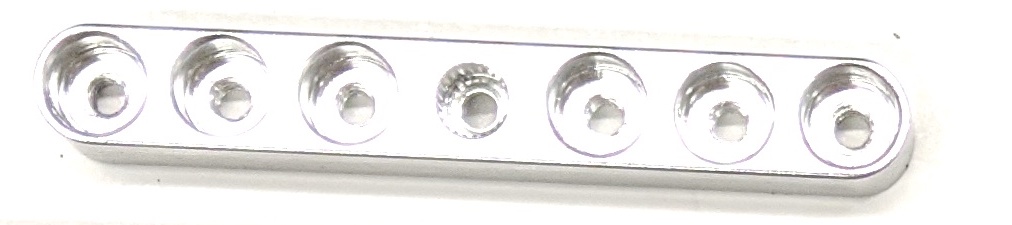
그림 6. 앞면에서 삽입한 나사로 조인 고정대 뒷면의 샤프트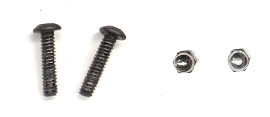
그림 7. 4-40, 3/4인치 긴 나사 및 4-40 캡 너트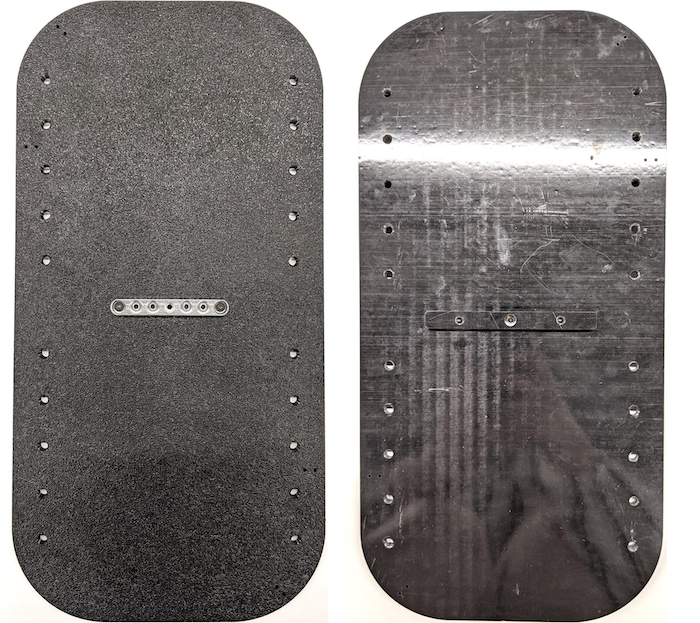
그림 8. 스마트폰 마운트의 후면(왼쪽) 및 전면(오른쪽)
3단계: 스마트폰 클램프 부착
스마트폰 클램프를 부착하려면 다음 단계를 따릅니다.
ABS 절단 클램프 모양에 따라 네오프렌 시트를 자르되, 그림 9와 같이 양쪽 끝에서 1인치씩 남겨둡니다. 그에 따라 네오프렌 시트를 자른 다음, 그림 8과 같이 ABS 절단 클램프에 조각을 부착합니다.
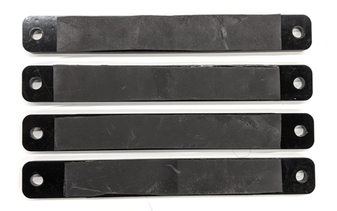
그림 9. 네오프렌 시트가 적용된 ABS 클램프나일론 엄지 나사와 스프링 와이어를 클램프에 부착합니다. 필요한 경우, 나일론 너트를 추가하여 나사 길이를 줄입니다.
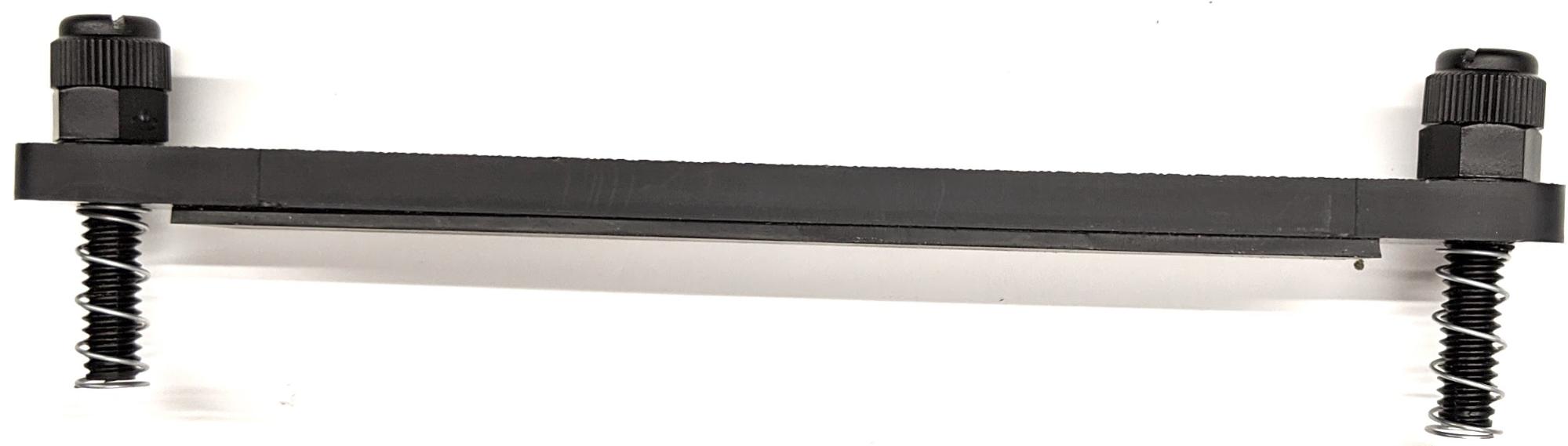
그림 10. 네오프렌 시트, 엄지 나사, 나일론 너트, 스프링 와이어가 있는 클램프그림 11에 표시된 것처럼 스마트폰 고정대의 나사 구멍에 스마트폰 클램프의 엄지 나사를 고정합니다. 스마트폰 크기에 따라 스마트폰 마운트의 위치를 조정할 수 있습니다.
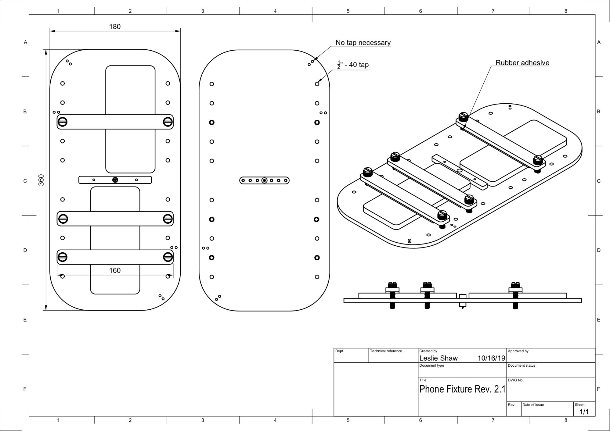
그림 11. 스마트폰 고정대의 기계 도면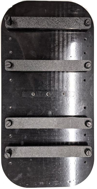
그림 12. 조립된 스마트폰 고정대
4단계: 슬라이딩 도어 레일 조립
상자의 상단과 하단에 슬라이딩 패널 레일을 앞쪽으로 고정합니다. 그림 13은 미리 뚫은 나사 구멍에 6-32 나사를 조인 모습입니다. 또는 자동 태핑 나사를 사용할 수 있습니다.
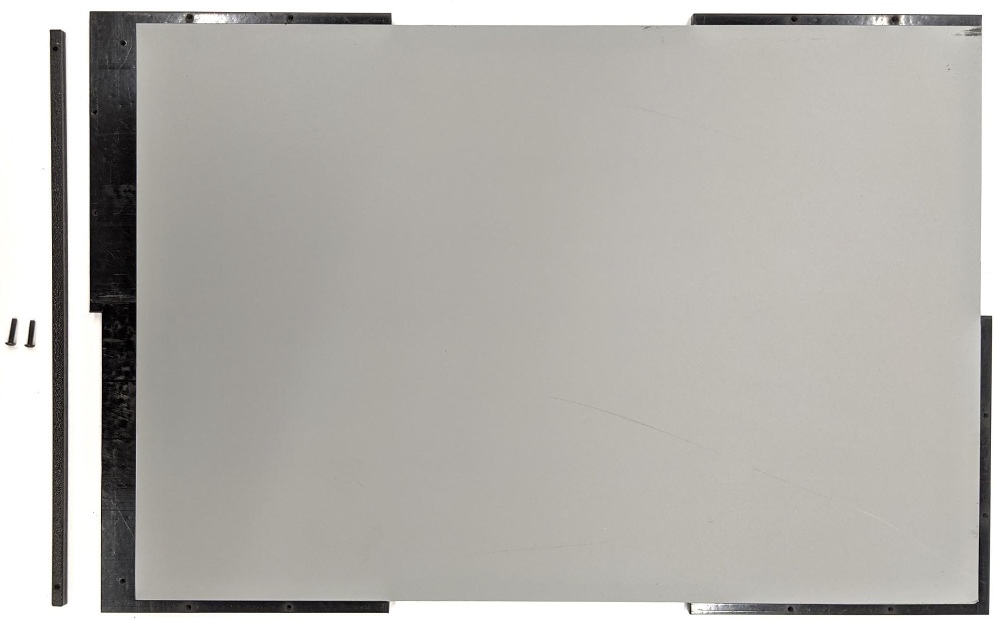
그림 13. 상자 상단과 하단에 고정된 슬라이딩 패널 레일
5단계: 조명 부착
조명 브래킷과 산광기를 부착하려면 다음 단계를 따릅니다.
핸들 피스 2개를 겹치고 6-32 나사(또는 자동 태핑 나사)를 사용하여 조립합니다.
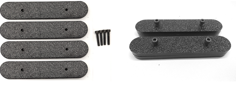
그림 14. 센서 퓨전 상자 핸들 피스 및 조립4개의 4-40 나사, 너트 및 도토리 너트를 준비하여 조명 키트의 마운트 브래킷을 상자 벽면에 고정합니다.
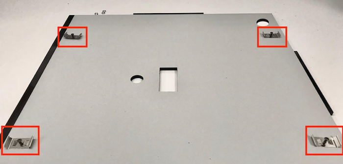
그림 15. 상자 내부 벽면의 4-40 나사 및 조명 브래킷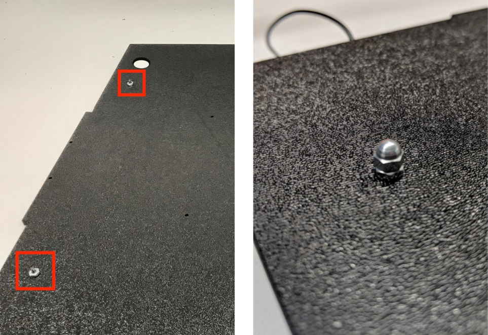
그림 16. 상자 바깥쪽에서 나사에 부착된 볼트와 도토리 볼트전구를 감싸도록 산광기를 적절한 크기로 자릅니다(조명이 산광기와 함께 제공되는 경우에는 필요하지 않음).
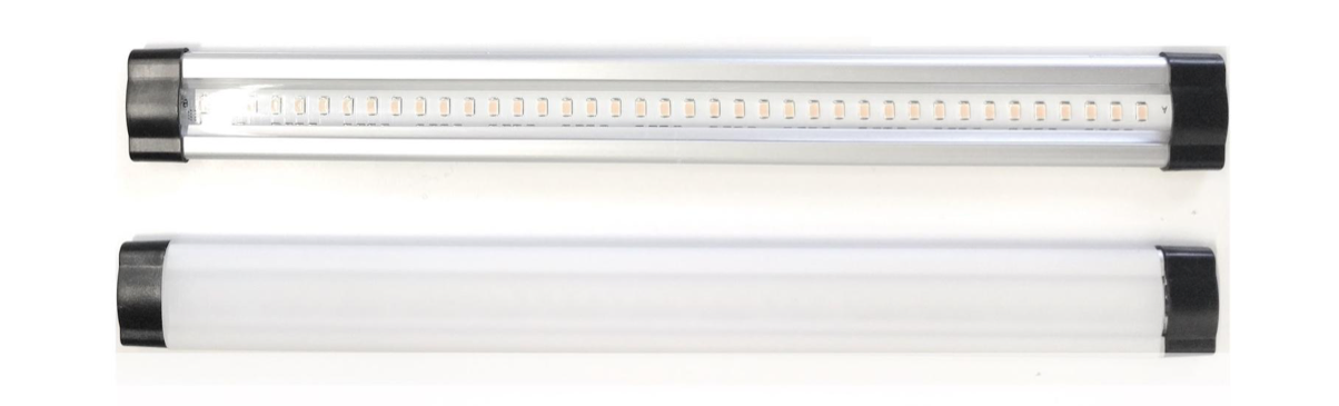
그림 17. 전구 및 산광기산광기로 전구를 감싸고 뒷면에 테이프를 붙입니다.
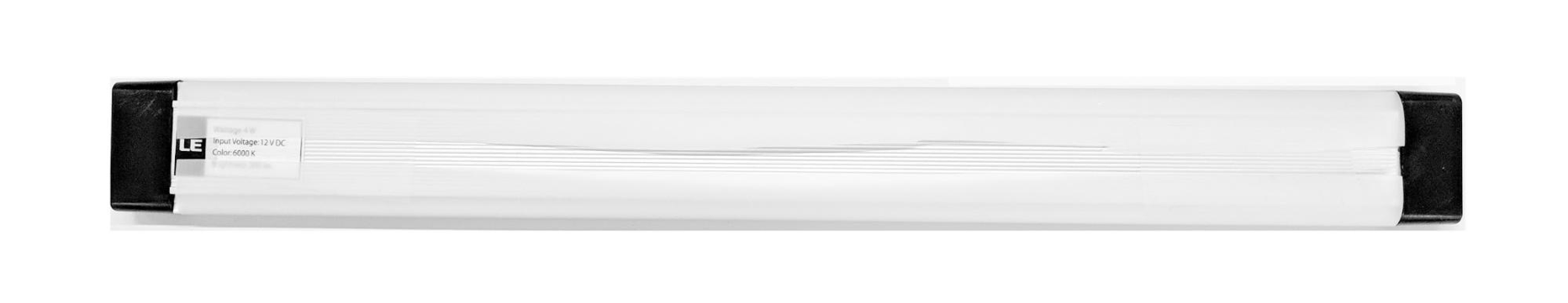
그림 18. 뒷면에 테이프를 붙인 전구와 산광기조명을 브래킷에 끼웁니다(딱 맞을 수 있음).
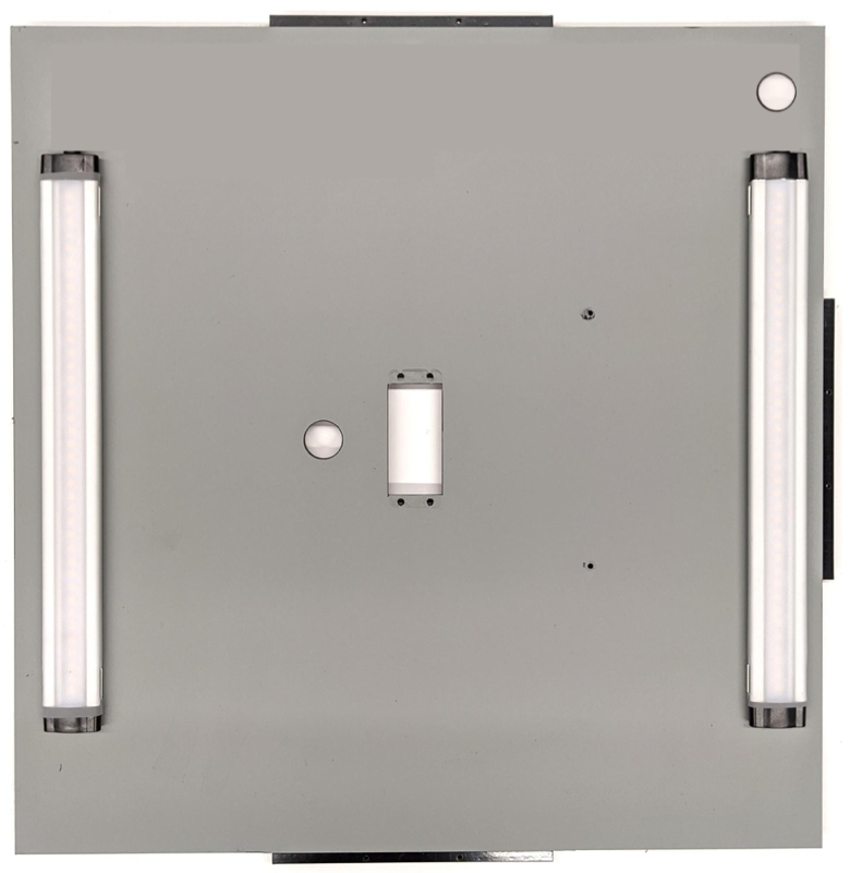
그림 19. 조명이 브래킷에 장착됨
6단계: 서보 플레이트에 스마트폰 고정대 부착
스마트폰 고정대를 서보 플레이트에 부착하려면 다음 단계를 따릅니다.
서보를 벽면에 고정하기 위해 4개의 6-32 나사와 한 개의 서보 플레이트를 준비합니다. 서보를 내부 벽면에 고정한 다음 안쪽에서 외부 벽면의 서보 플레이트로 나사를 삽입합니다.
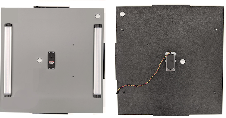
그림 20. 6-32 나사로 고정된 서보 및 서보 플레이트샤프트 중심을 서보의 회전 중심 쪽으로 밀어 닐록 너트로 스마트폰 고정대를 서보에 고정합니다.
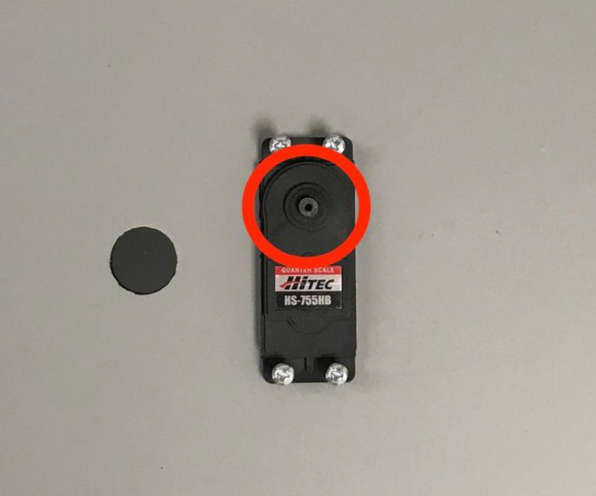
그림 21. 서보 장비
서보와 함께 제공되는 서보 나사를 사용하여 서보 암을 통해 스마트폰 고정대를 서보 장비에 고정합니다(1.2N*m 또는 8.9in*lbf).
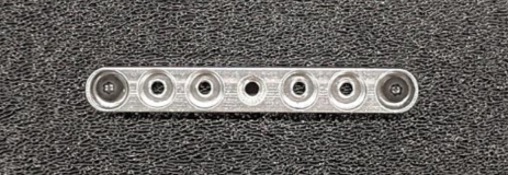
그림 22. 서보 암
7단계: 최종 조립
센서 퓨전 상자 조립을 완료하려면 다음 단계를 따릅니다.
Android 13부터 센서 퓨전 테스트 장비는 Android 13 Arduino 조명 컨트롤러와 함께 제공됩니다. Android 12 이하에서는 센서 퓨전 장비가 6채널 Arduino 컨트롤러 또는 Canakit 컨트롤러와 함께 제공되었습니다. Android 11~Android 12를 실행하는 기기는 Android 13 컨트롤러나 6채널 Arduino 컨트롤러, Canakit 컨트롤러와 호환됩니다. 서보 확장 프로그램을 서보 컨트롤러의 어느 채널에든 연결합니다. 여기서 GND는 검은색 와이어, VCC는 빨간색 와이어, SIG는 노란색 와이어입니다.
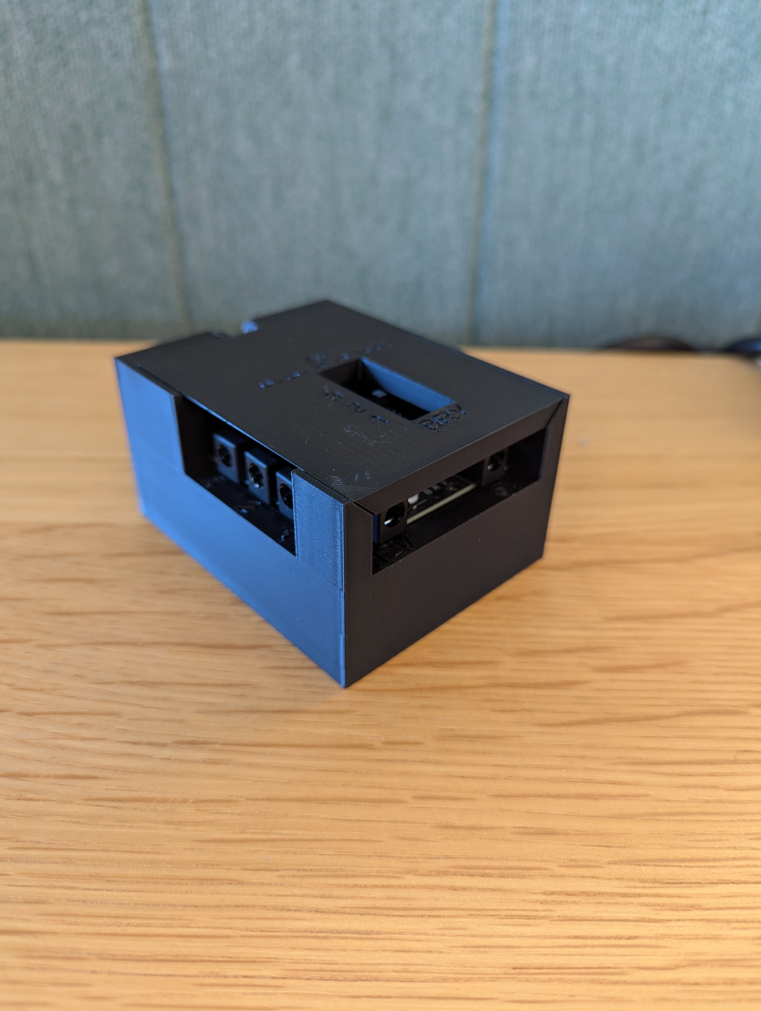
그림 23. Arduino 조명 컨트롤러 Rev3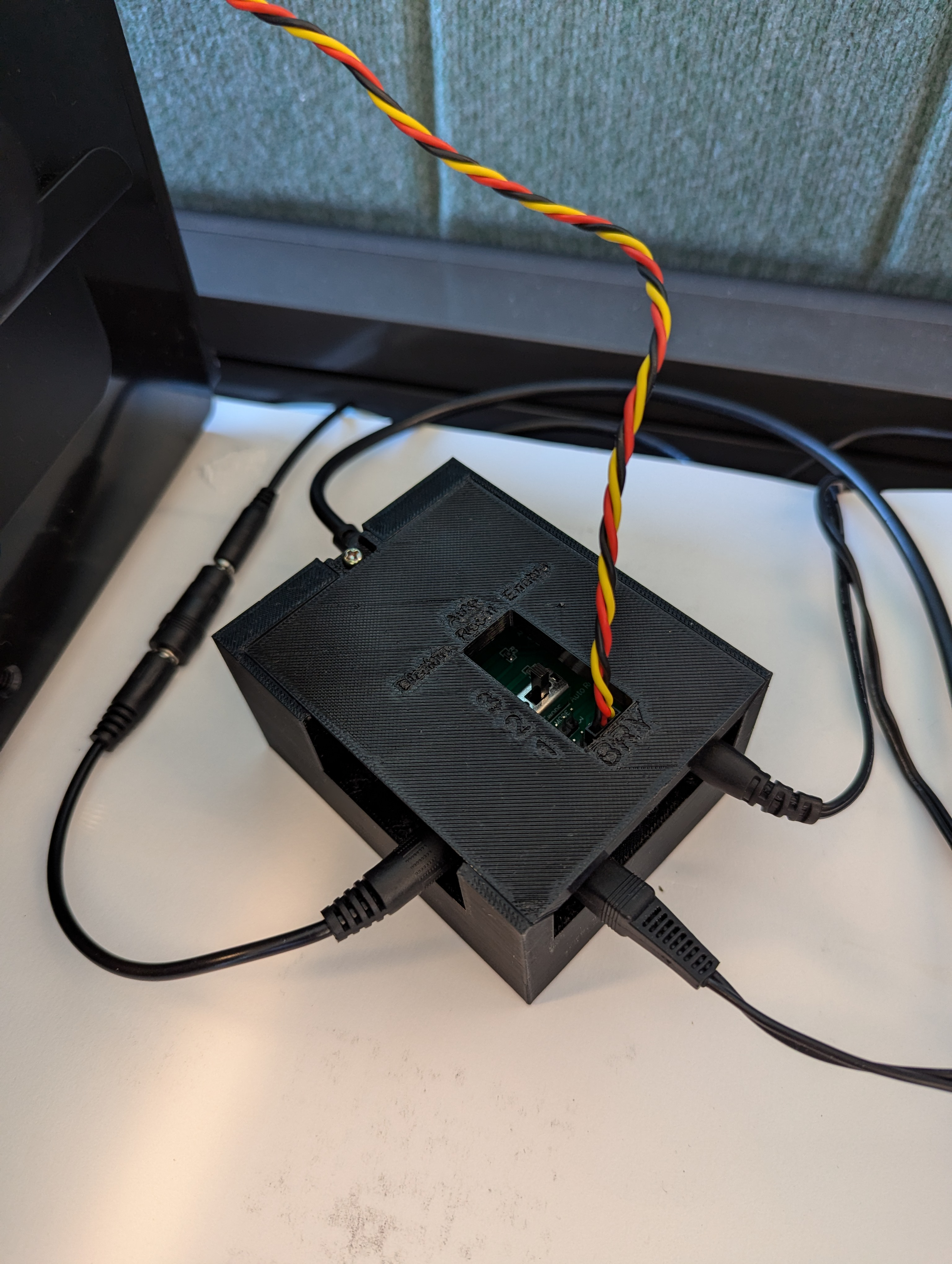
그림 24. Arduino 조명 컨트롤러 Rev3 연결 샘플상자를 테이프로 이어 붙인 다음 나사로 부품을 조입니다(일부 부품에 미리 구멍을 뚫어야 할 수 있음).
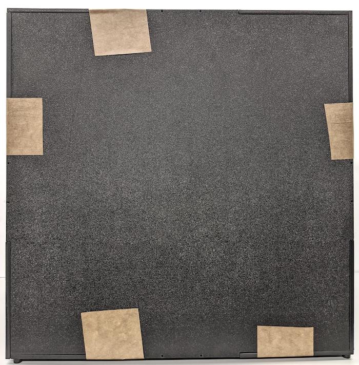
그림 25. 테이프를 붙인 센서 퓨전 테스트 장비
Android 15 이상의 경우 현지 인쇄소와 협력하여 코드베이스의
test/sensor_fusion디렉터리에 포함된 checkerboard.pdf 파일을 18x18인치 용지에 출력하고(용지 너비로 격자무늬 패턴이 있음) 스마트폰 고정대 반대편 벽에 차트를 테이프로 붙입니다.망원 카메라와 같이 시야가 좁은 카메라의 경우에는 현지 인쇄소와 협력하여 비례적으로 크기가 조정된 격자무늬 버전을 만듭니다. 예를 들어 50%로 조정된 차트는 9x9인치 용지에 출력됩니다.
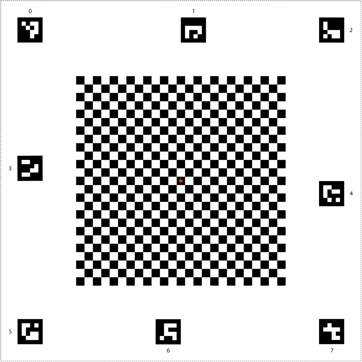
그림 26. Android 15 이상의 격자무늬 차트
고정대에 카메라를 두었을 때 카메라가 격자무늬 중앙의 빨간색 점을 바로 향하도록 해야 합니다(그림 27 참고).
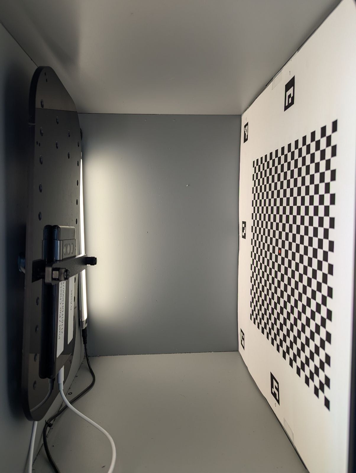
그림 27. 격자무늬를 인쇄한 후 스마트폰 고정대의 반대쪽 벽에 테이프로 붙인 모습