
The Gen2 camera ITS-in-a-box consists of an aluminium box that's laser cut from computer-aided design (CAD) drawings, a printed test chart, and a device under test (DUT). The Gen2 camera ITS-in-a-box has the same capabilities as the regular camera ITS-in-a-box but includes a three-stage lighting system with high-quality LED modules, an improved motor that's robust and provides feedback, and full metal construction to improve structural rigidity and reduce light leakage.
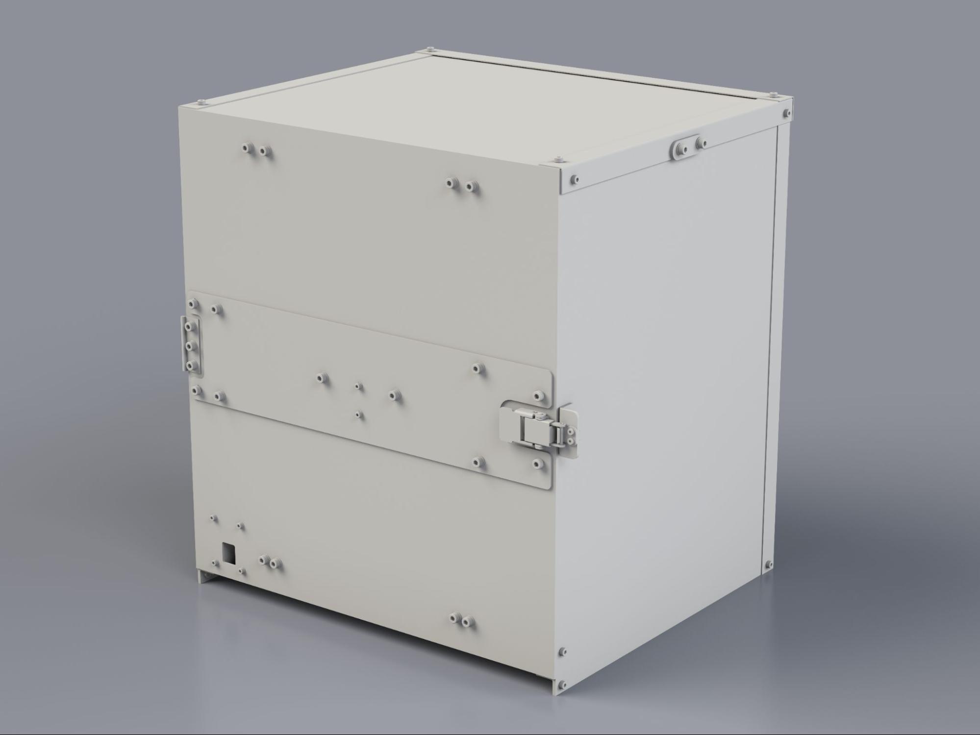
Figure 1. Gen2 camera ITS-in-a-box.
How to use the Gen2 camera ITS-in-a-box
To use the Gen2 camera ITS box, follow these steps:
- Purchase the Gen2 ITS box.
- Set up the controller and mount the DUT.
- Run the camera ITS tests.
- Retrieve the results from the DUT.
Purchase a Gen2 camera ITS-in-a-box
We recommend purchasing the Gen2 camera ITS-in-a-box from one of the following qualified vendors.
Wuxi BioHermes Bio&Medical Technology Co., Ltd.
China: 88 West Meiliang Road. Mashan. Wuxi, Jiangsu 214092
http://www.biohermes.com
luweijie@biohermes.com.cn
China: +86-510-85385897 ext 2121Byte Bridge Inc.
USA: 1502 Crocker Ave, Hayward, CA 94544-7037
China: 22F #06-08, Hongwell International Plaza Tower A, 1600 West Zhongshan Road, Xuhui, Shanghai, 200235
https://www.bytebt.com
androidpartner@bytebt.com
USA: +1-510-373-8899
China: +86-400-8866-490
Video tutorial
This is a video tutorial of how to set up the Gen2 camera ITS-in-a-box:
Set up the controller for testing
Follow these steps to set up the Gen2 camera ITS-in-a-box controller for testing.
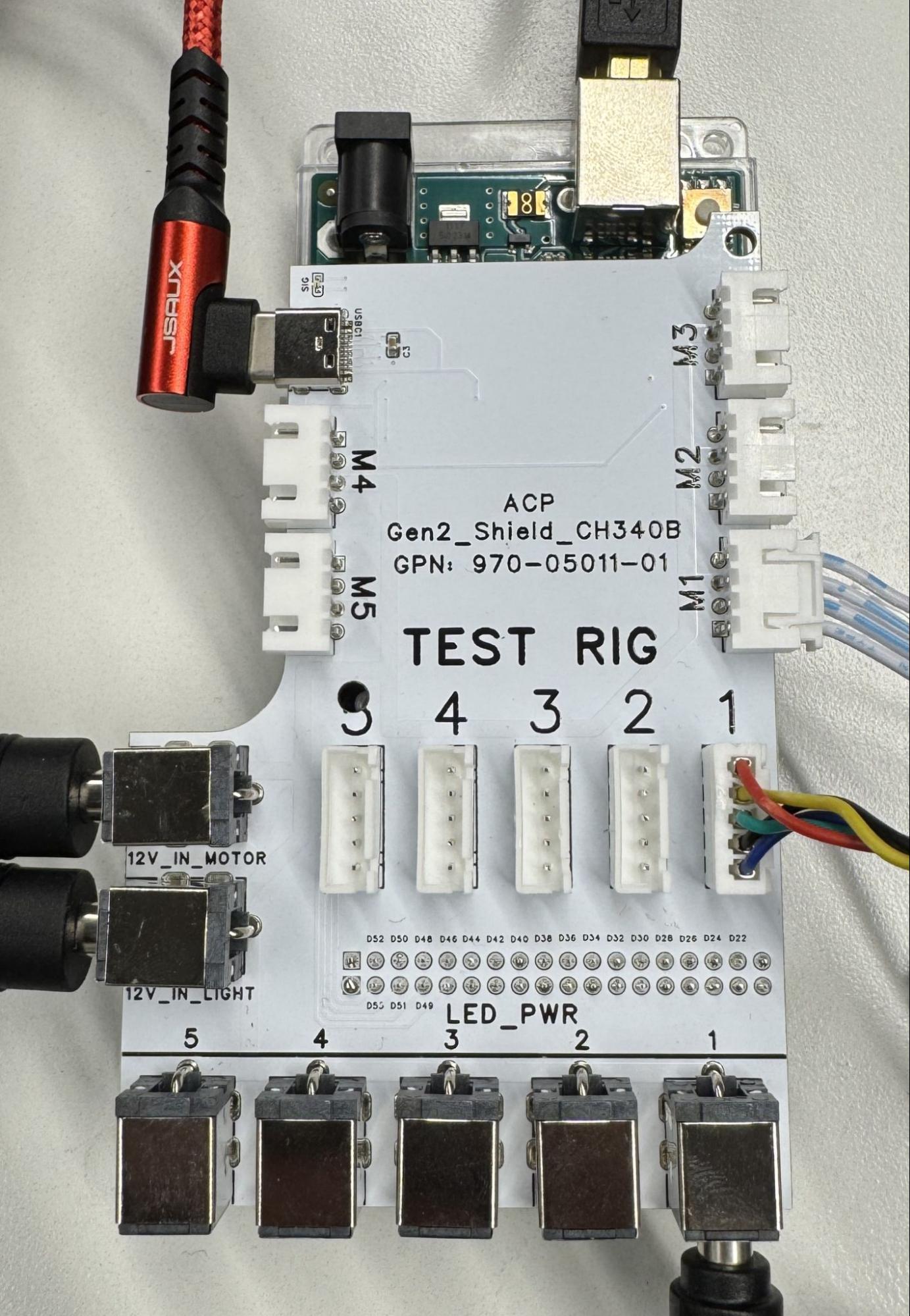
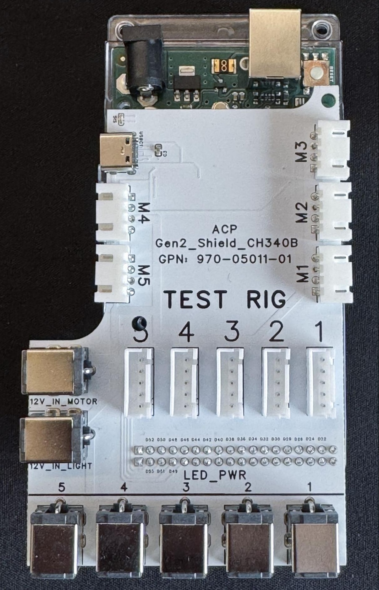
Figure 2. Gen2 controller with (left) and without connections (right).
- Place the Gen2 rig at your desired location.
Connect the cables to the appropriate ports as follows:
- 4-pin cable to the M1 port.
- 5-pin cable to the TEST RIG - 1 port.
- Barrel plug to the LED_PWR - 1 port.
- Barrel plugs of the two power supplies to the 12V_IN_MOTOR and 12V_IN_LIGHT ports.
- USB-A to USB-C cable to the M4 USB-C port.
- USB-A to USB-B cable to the M3 USB-B port.
- Power cords from the power supplies to a power outlet.
- USB-A end of the USB-A/C and USB-A/B cables from the controller to your host.
The controller firmware is available at gen2_production_v2.ino.
Frequently asked questions (FAQs)
The following are frequently asked questions about the Gen2 camera ITS-in-a-box.
Chart
Q: My chart is damaged, how can I get a new chart?
A: To get a new chart, reach out to one of our qualified vendors, Biohermes or Byte Bridge Inc.
Q: Do I have the correct chart?
A: There are two versions of the chart. Figure 3 shows the chart designed
for scene_ip testing (left) and the chart designed for
scene_ip, sensor_fusion, and scene_flash testing (right).
Figure 3. Chart versions.
Motor
Q: My rig connects, but the motor doesn't maintain its position. Is this normal?
A: Yes, this is normal in the initial test cycle. After the initial test cycle is complete, the motor maintains its position.
Q: How is the LSS-HT1 motor in the Gen2 rig different from the HS-755MG motor in the sensor fusion rig?
A: The LSS-HT1 motor in the Gen2 rig improves the accuracy, precision, build quality, and feedback of the rig. The motor also provides extensive parameter controls.
Q: My motor flashes and doesn't move. What should I do?
A: This indicates that an obstruction is blocking the motor. Inspect the DUT
and rotating plate for obstructions or tangled cables. After resolving the
issue, send the command #0RESET<cr> to reset the motor and continue
testing.
Q: Where can I find a datasheet for the motor (LSS-HT1)?
A: You can find documentation on the LSS-HT1 motor at the Lynxmotion website.
LED
Q: How do I determine if my LED bars install correctly?
A: Refer to Figure 4 for an example LED bar installation. Ensure that the white line on the LED board aligns with the 3D-printed holder, and the LEDs are connected and seated correctly.
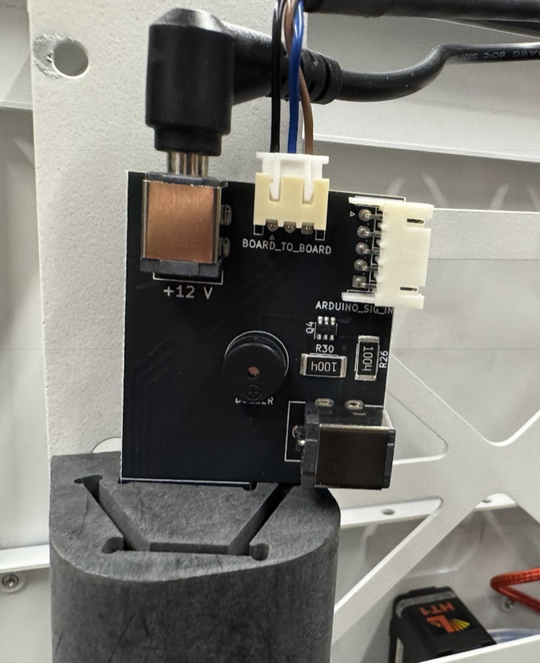
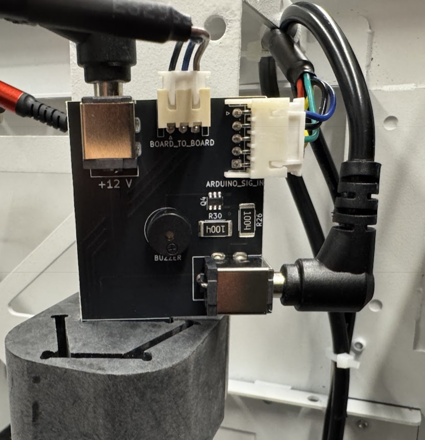
Figure 4. LED bar installation with (left) and without connections (right).
Controller
Q: What are the designated channels for the motor and LEDs?
A: Channel 0 for the motor. Channel 1 for the LEDs.
Q: How do I test the hardware?
A: Send the command f11 to the controller (Arduino Mega) to initiate a
test sequence for the lighting. The sequence cycles through three distinct
lighting stages and briefly activates the buzzer multiple times. To test the
motor, use the Lynxmotion LSS configuration software available from
Lynxmotion.