
This page provides information on how to purchase or assemble a Sensor Fusion
Box. The Sensor Fusion Box is used in the CameraITS sensor_fusion test and
multi-camera sync test. It provides a consistent test environment for
measuring timestamp accuracy of sensors for Android
devices, specifically camera image sensors and gyroscopes. It consists of
plastic box components that are laser cut from
computer-aided design (CAD) drawings and a Servo Control Box.
You can purchase a Sensor Fusion Box or build your own.
Purchase a Sensor Fusion Box
We recommend purchasing a Sensor Fusion Box from one of the following qualified vendors.
Byte Bridge Inc.
USA: 1502 Crocker Ave, Hayward, CA 94544-7037
China: 22F #06-08, Hongwell International Plaza Tower A, 1600 West Zhongshan Road, Xuhui, Shanghai, 200235
www.bytebt.com
androidpartner@bytebt.com
USA: +1-510-373-8899
China: +86-400-8866-490JFT CO LTD 捷富通科技有限公司 (previously known as MYWAY DESIGN)
China: No. 40, Lane 22, Heai Road, Wujing Town, Minhang District, Shanghai, China
Taiwan: 4F., No. 163, Fu-Ying Road, XinZhuang District, New Taipei City 242, Taiwan
www.jftcoltd.com
service@jfttec.com or its.sales@jfttec.com
China:+86-021-64909136
Taiwan: 886-2-29089060
Build a Sensor Fusion Box
This section includes step-by-step instructions for assembling a Sensor Fusion Box from laser-cut acrylonitrile butadiene styrene (ABS) components (shown in Figure 1).
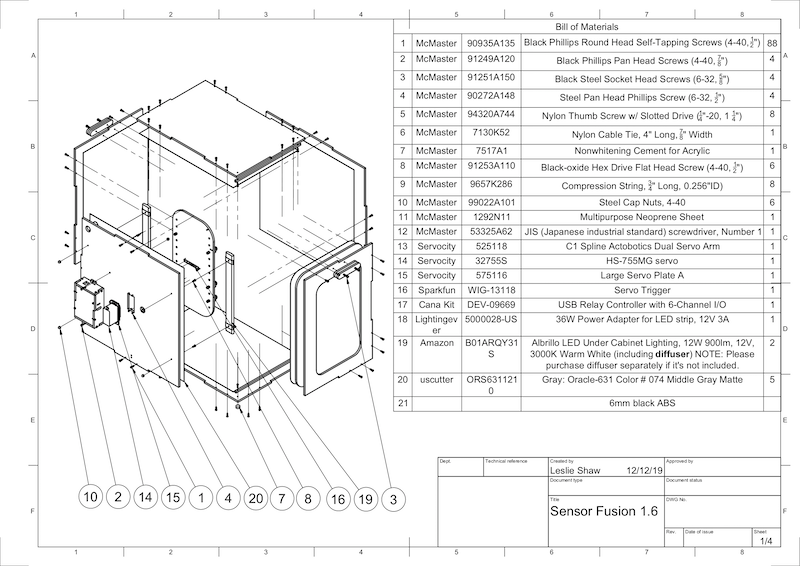
Figure 1. Mechanical drawing of Sensor Fusion Box components
Required tools
Before starting, ensure you have downloaded the technical drawings for the Sensor Fusion Box (included in the Sensor Fusion Box zip file) and have the following tools available:
- Phillips head screwdriver
- JIS head screwdriver
- Hex keys
- Power drill set
- X-ACTO knife
- Tape
Step 1: Apply vinyl stickers
After creating the ABS components with a laser cutter, apply vinyl stickers to the plastic box to get the proper color control on the interior of the test box:
Apply vinyl on the smooth side of the ABS as shown in Figure 2. For helpful tips on applying vinyl, refer to wikiHow.
Cut out the necessary holes on the vinyl with the exacto knife.
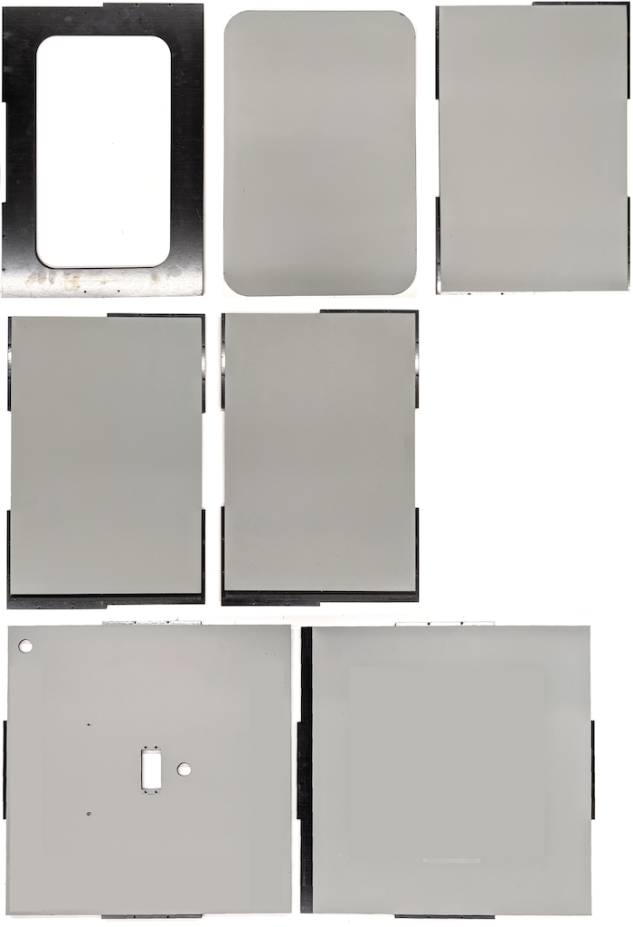
Figure 2. ABS pieces with vinyl applied on the smooth side (interior of the box)Using acrylic glue, glue the round ABS pieces onto the four corners of the bottom panel.
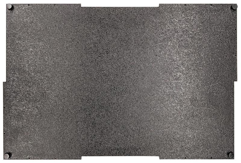
Figure 3. Bottom panel with round ABS pieces glued to the four corners.
Step 2: Prepare phone mount and attach servo mount
To prepare the phone mount to attach to the servo:
Tap 20 holes on the phone fixture with a 1/4"-20 drill bit.
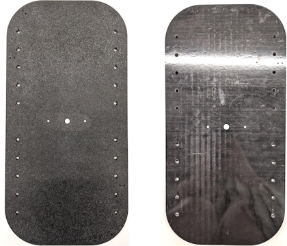
Figure 4. Phone fixture with tapped holesMake sure you have the ABS cut outs, nylon thumb screws, nylon nuts (for adjusting screw height if necessary), the C1 spline actobotics dual servo arm, 4-40 screws, and compression springs.
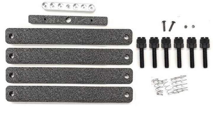
Figure 5. Phone mount partsApply the 4-40 screws and tighten (1.2 N*m or 8.9 in*lbf) the servo arm to the back of the phone mount. Using the same screws and 4-40 cap nuts, tighten the phone divider ABS cut out on the front side of the phone mount.
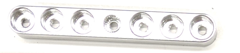
Figure 6. Shaft on the back of fixture, tightened by screws applied from the front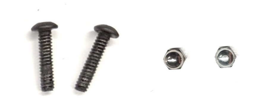
Figure 7. 4-40, 3/4" long screws and 4-40 cap nuts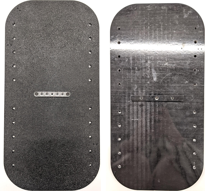
Figure 8. Back (left) and front (right) of the phone mount
Step 3: Attach phone clamps
To attach the phone clamps:
Cut the neoprene sheet according to the shape of the ABS cut-out clamps, but leave one inch shorter from both ends as shown in Figure 9. After cutting the neoprene sheet accordingly, apply the pieces to the ABS cut-out clamps as in Figure 8.
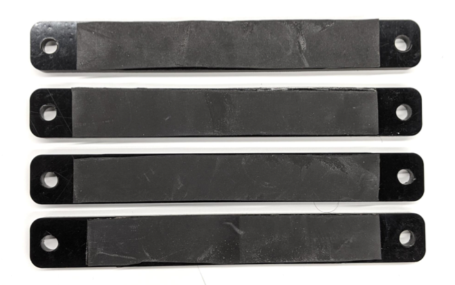
Figure 9. ABS clamp with neoprene sheet appliedAttach nylon thumb screws and spring wire to the clamp. Add nylon nuts to reduce screw length, as needed.
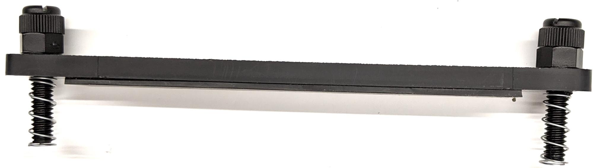
Figure 10. Clamp with neoprene sheet, thumb screws, nylon nuts, and spring wireScrew the phone clamps' thumb screws into the tapped holes of the phone fixture as shown in Figure 11. You can adjust the location of the phone mounts depending on the size of the phones.
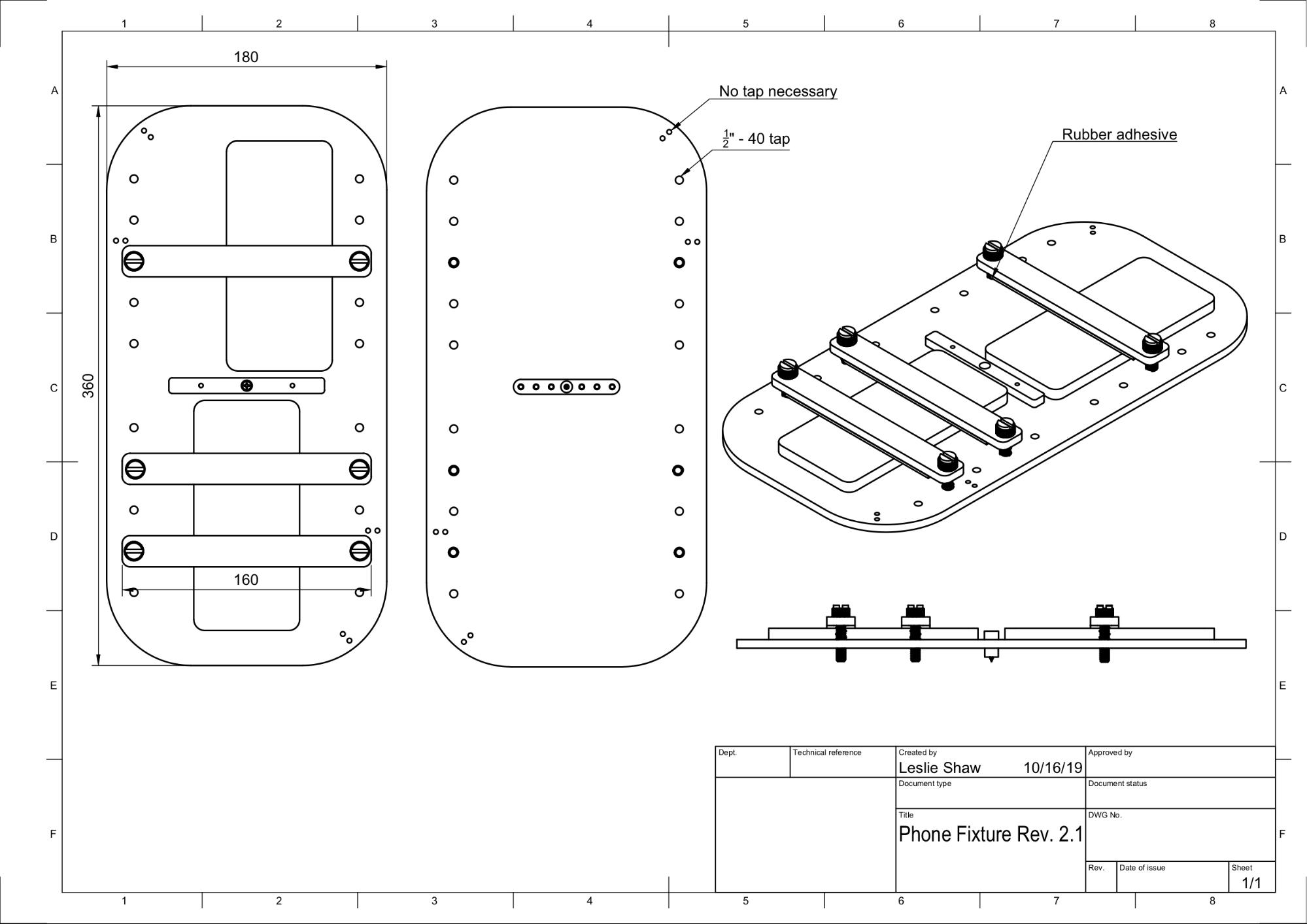
Figure 11. Mechanical drawing of the phone fixture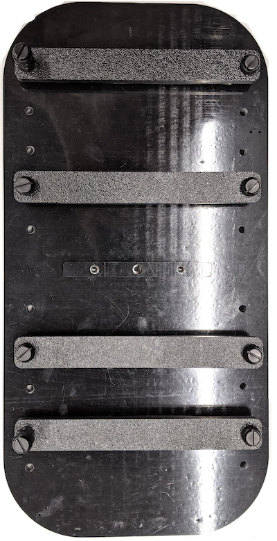
Figure 12. Assembled phone fixture
Step 4: Assemble sliding door rail
Fix sliding panel rails on the top and bottom of the box toward the front. Figure 13 shows 6-32 screws on pre-tapped holes. Alternatively, you can use self-tapping screws.
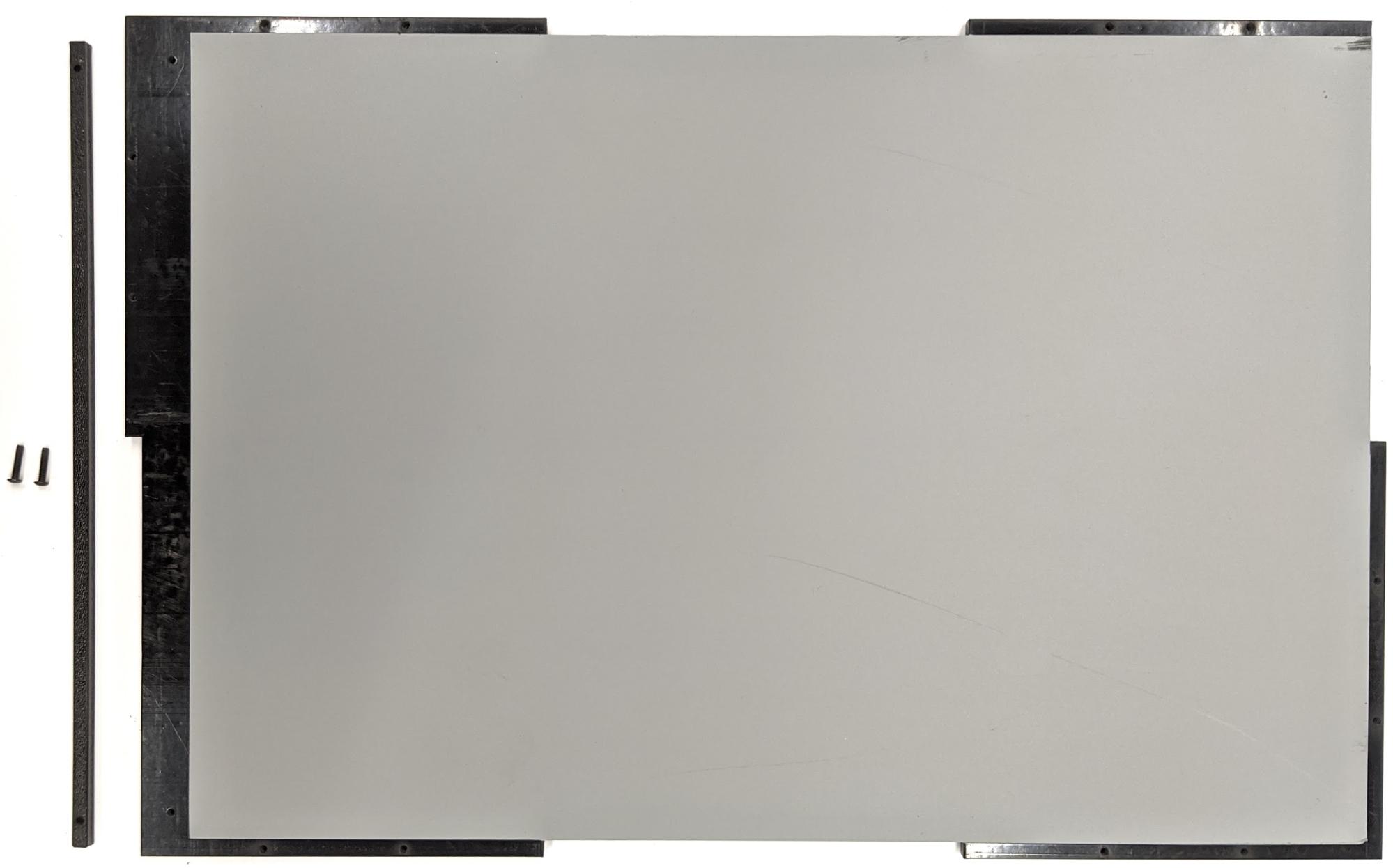
Figure 13. Fixed sliding panel rail on top and bottom of box
Step 5: Attach lighting
To attach the light brackets and diffuser:
Stack two handle pieces on top of each other and assemble them using 6-32 screws (or use self-tapping screws).
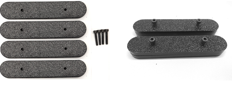
Figure 14. Sensor Fusion Box handle pieces and assemblyPrepare four 4-40 screws, nuts, and acorn nuts to fix the mounting bracket from the lighting kit to the wall of the box.
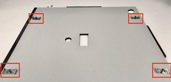
Figure 15. 4-40 screws and light bracket on the interior wall of the box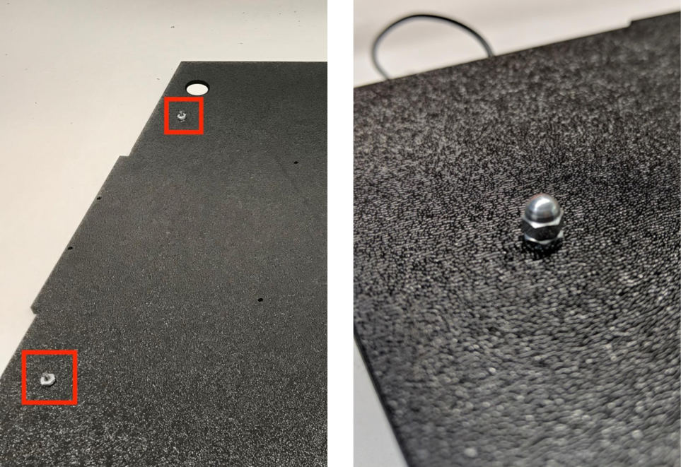
Figure 16. Bolts and acorn bolts applied to the screws from the exterior of the boxCut the light diffuser to an appropriate size to wrap the light strips (not required if the lights come with the diffuser).
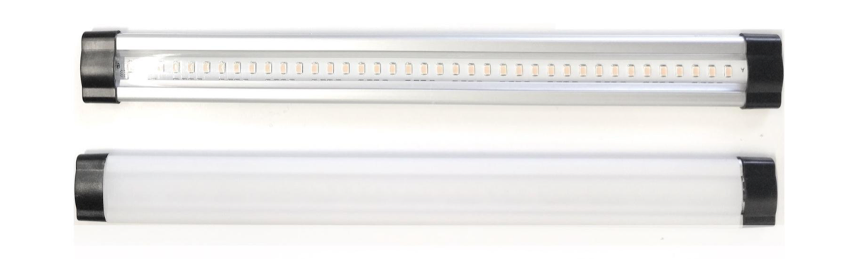
Figure 17. Light strips and light diffusersWrap the light diffuser around the strip and tape it at the back.
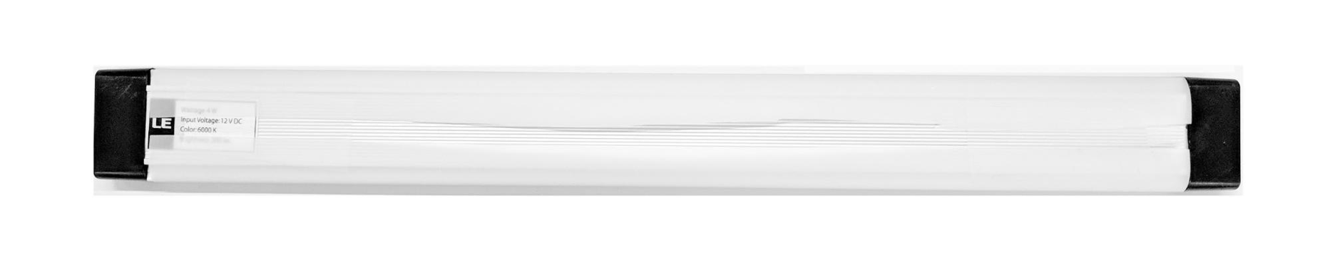
Figure 18. Light strips and light diffusers taped from the backSnap the lights into the brackets (can be a tight fit).
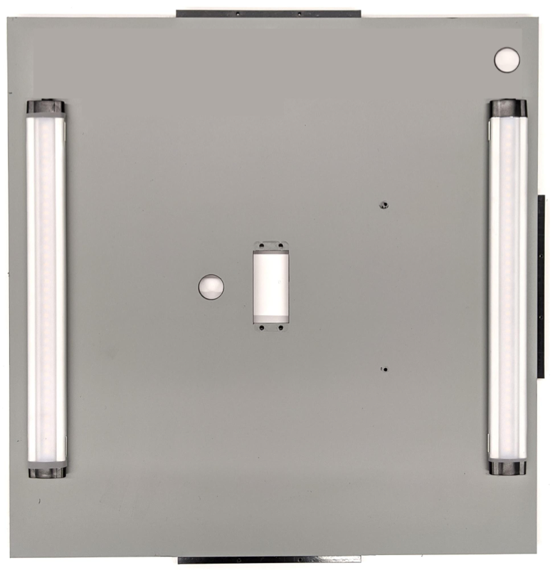
Figure 19. Lights mounted in brackets
Step 6: Attach phone fixture to servo plate
To attach the phone fixture to the servo plate:
Prepare four 6-32 screws and a servo plate to fix the servo onto the wall. Fix the servo onto the interior wall and insert the screws from the inside into the servo plate on the exterior wall.
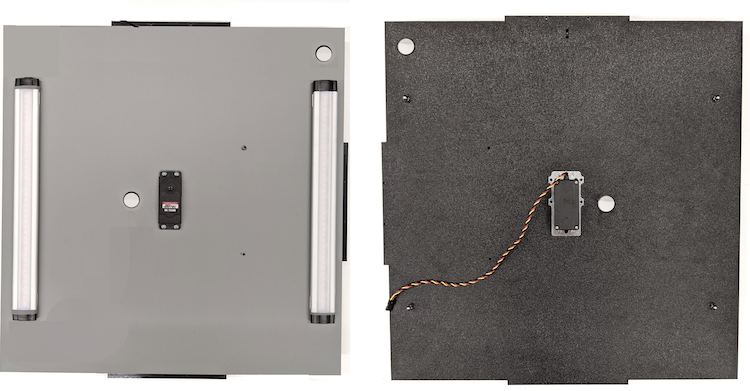
Figure 20. Servo and servo plate held in place with 6-32 screwsSecure the phone fixture onto the servo with nylocks (pushing the center of the shaft into the servo's rotation center).
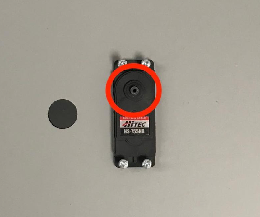
Figure 21. Servo gear
Using the servo screw that came with the servo, screw (1.2 N*m or 8.9 in*lbf) the phone fixture onto the servo gear through the servo arm.
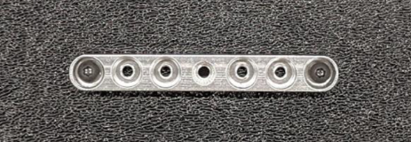
Figure 22. Servo arm
Step 7: Final assembly
To complete assembly of the Sensor Fusion Box:
From Android 13, the sensor fusion test rig comes with the Android 13 Arduino lighting controller. (In Android 12 or lower, the sensor fusion rig shipped with a 6-channel Arduino controller or a Canakit controller. Devices running Android 11 to Android 12 are compatible with the Android 13 controller, 6-channel Arduino controller, or Canakit controller.) Connect the servo extension to any channel of the servo controller, where GND corresponds to black wire, VCC corresponds to the red wire, and SIG corresponds to the yellow wire.
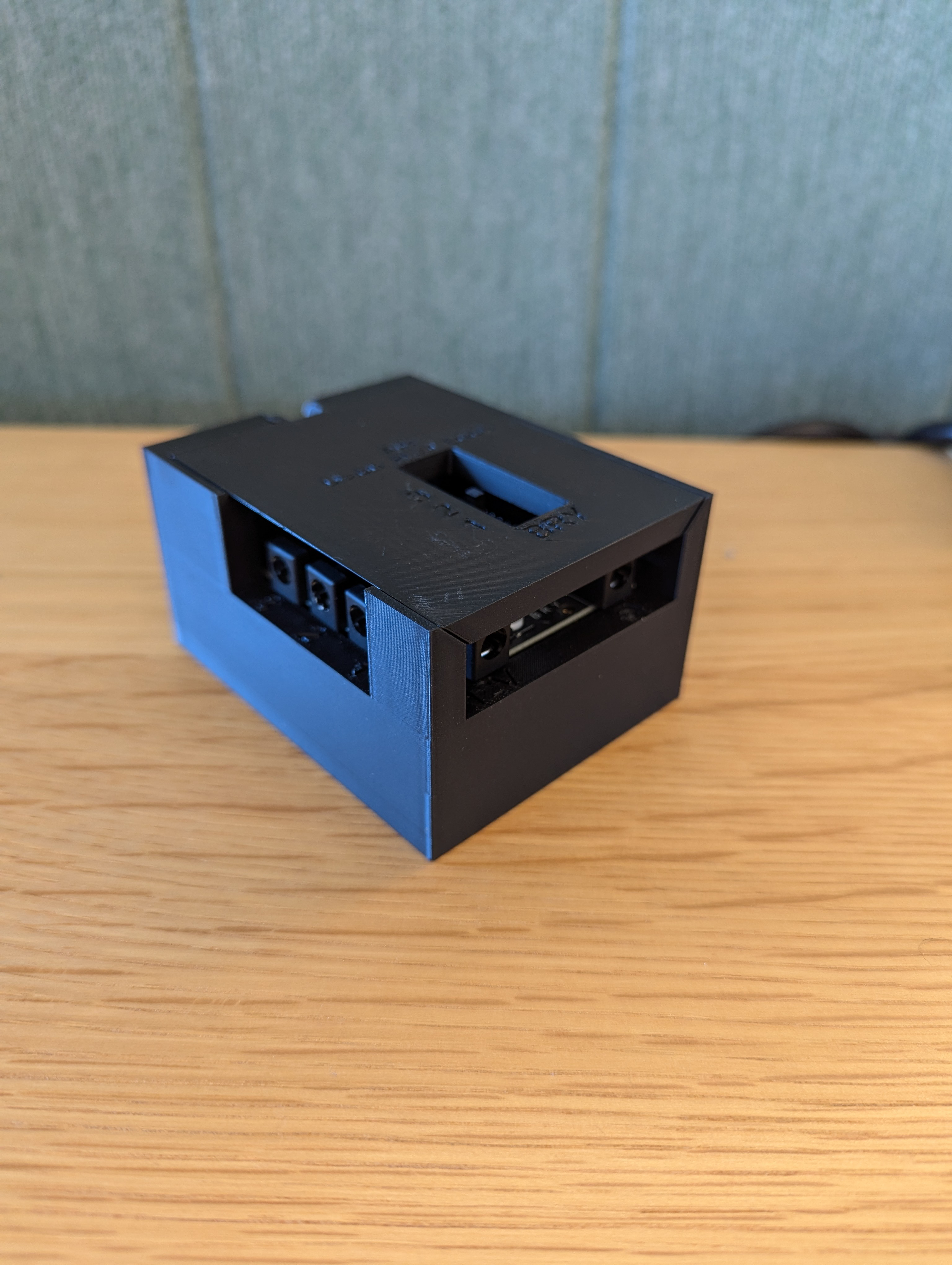
Figure 23. Arduino Lighting Controller Rev3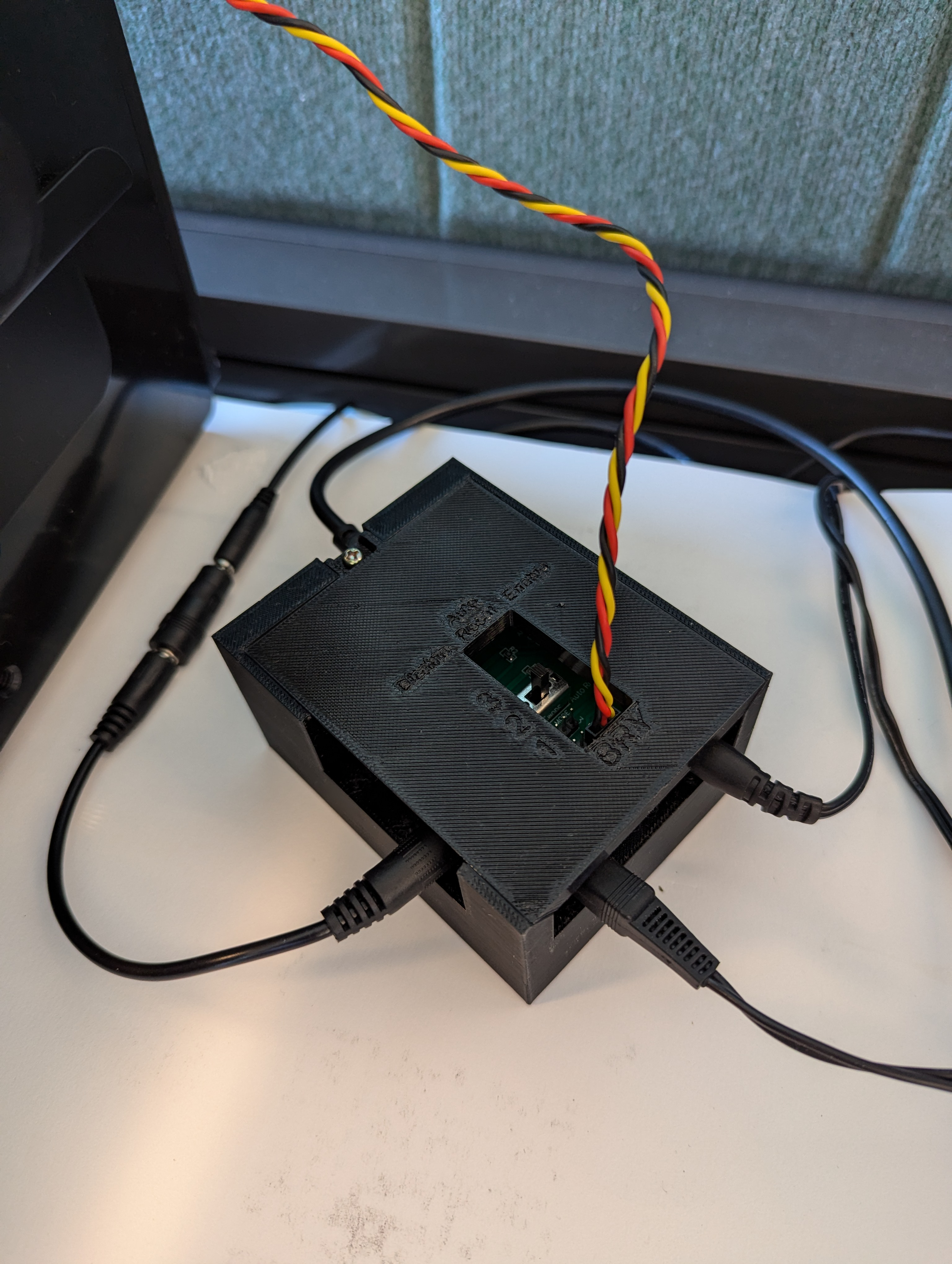
Figure 24. Arduino lighting controller Rev3 connection sampleTape the box together, then screw the parts together (you might need to pre-drill holes in some parts).
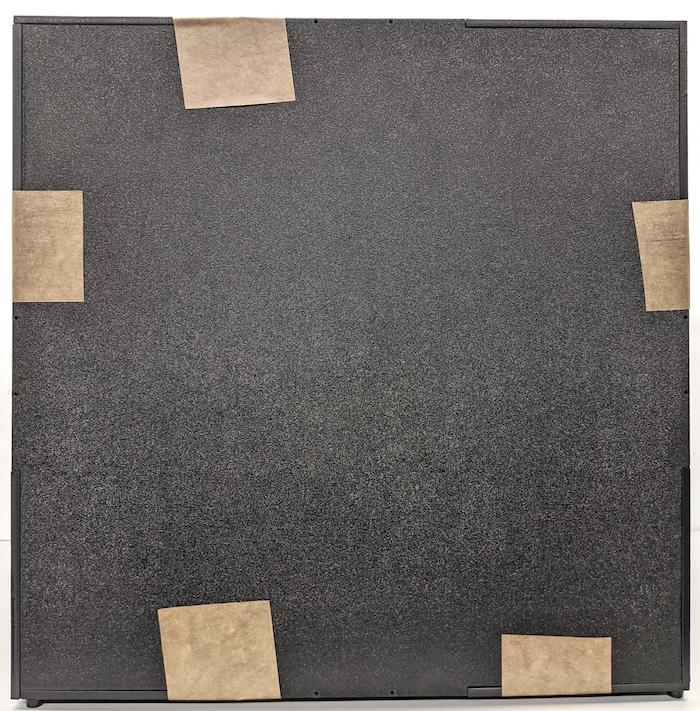
Figure 25. Taped sensor fusion test rig
For Android 15 or higher, work with your local print shop to print out the checkerboard.pdf file (included in the
test/sensor_fusiondirectory of the codebase) on 18 x 18 inch paper with the checkerboard pattern the width of the paper, and tape the chart on the wall opposite the phone fixture.For cameras with smaller fields of view, such as telephoto cameras, work with your local print shop to create proportionally scaled versions of the checkerboard. (For example, a 50% scaled chart would be printed on 9 x 9 inch paper.)
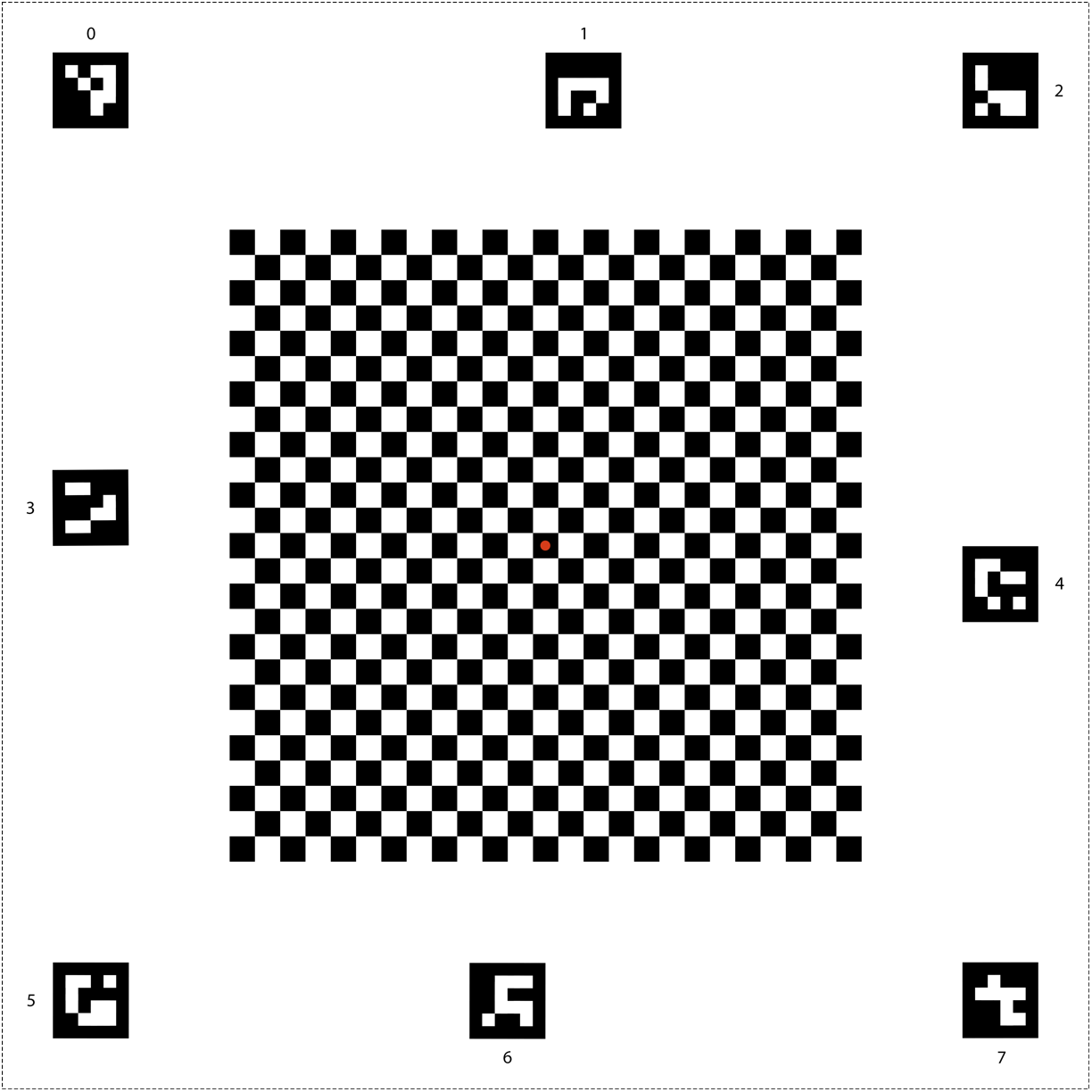
Figure 26. Checkerboard chart for Android 15 or higher.
Make sure the red dot in the center of the checkerboard is directly facing the camera when placed on the fixture, as shown in Figure 27.
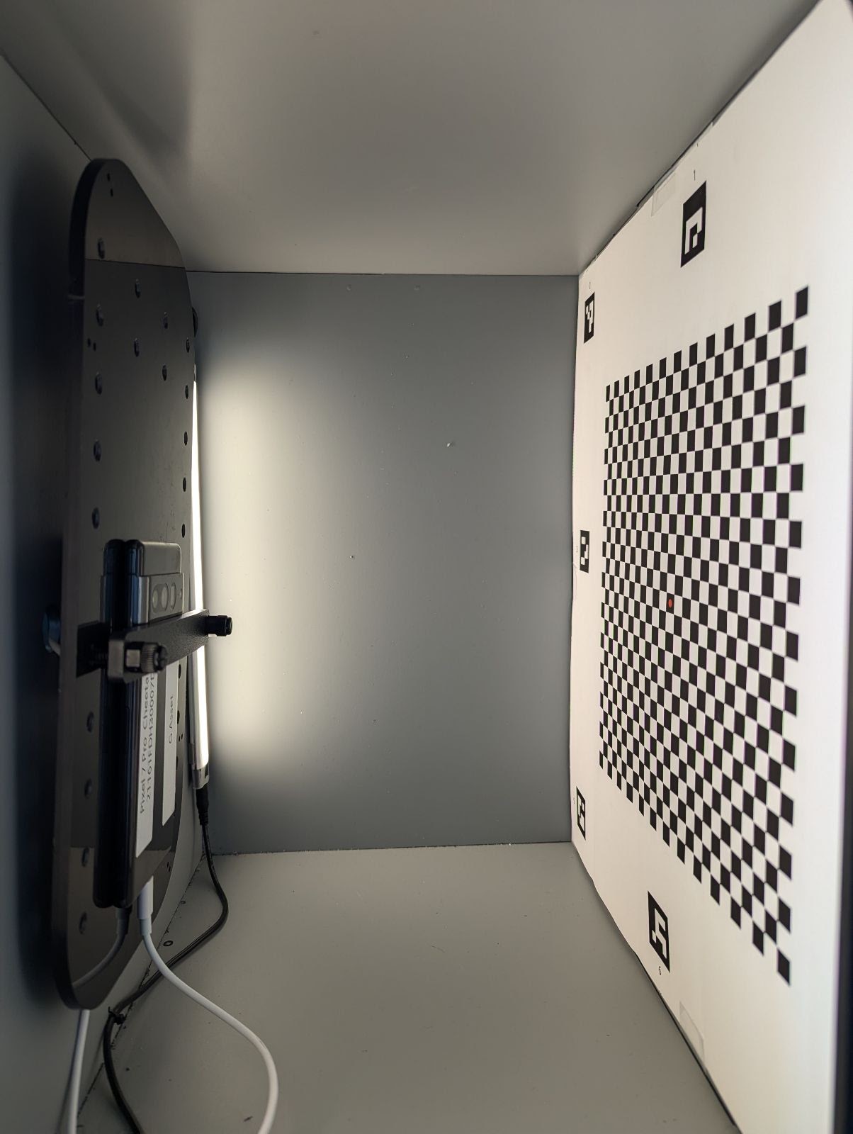
Figure 27. Checkerboard printed and taped to the opposite wall of phone fixture.