
Use the safety design toolchain to deliver a safety monitor solution generated from a Figma design document. Use this series of tools in sequence.
The safety design compiler produces safety artifacts to drive subsequent code generation for building the safety monitor. The separation between design compilation and code generation allows the code generator to achieve an ISO-26262 rating of TCL-3.

Figure 1. Safety design toolchain.
After the compiler generates artifacts, the toolchain creates a report that an OEM safety engineer can inspect to validate the artifacts generated from the Figma design.

Figure 2. Safety design toolchain workflow.
Design compiler inputs
The serialized design document represents a UI design imported from a design tool and processed with a toolkit schema. The file contains this information parsed from the design:
- Complete node tree of a design
- Images and components
- Metadata such as name, version, and last modification date
The root nodes of the design must be defined in the nodes list and must be the root nodes for the safety-relevant elements identified in the design.
This file integrates with Android Automotive OS to render the instrument cluster and displays the non-safety-relevant elements with a high availability renderer (HAR) running on SDV Media as an overlay to display the safety-relevant elements to the user.
The design compiler uses DesignCompose customizations to generate output to toggle the visibility of safety-critical elements in the design. The design is rendered headless with Impeller. Between customization changes, the system issues screenshot commands to the rendering backend to generate image artifacts.

Figure 3. Sample Figma design file to build safety monitor.
Output directory
This is the location on the local file system where the compiler stores the generated artifacts.
JSON configuration file
Most often, an OEM safety engineer authors the JSON configuration file, which contains metadata that captures the vehicle safety-relevant information not captured in a UI design. This file contains this data:
Design element designated as root of the safety-relevant display. This design element is sized to the vehicle display. Size must have the same resolution as the display. All safety-relevant elements must be descendants of this element. They needn't be direct descendants, but nested in intermediate nodes. This root is the root node object, and its name must match a node in the design document.
Target display for the design. To support UIs with elements across multiple displays, the config file can specify more than one design, each design targeted to be displayed on a separate screen.
Dictionary of vehicle bus signal names to associated UI elements. Keys and values of this dictionary are:
Keys: Vehicle bus signal name to contain meaning so that when this signal is active, the associated UI element is shown. When the signal is inactive, the associated UI element isn't shown.
Values: Figma node ID for the safety-relevant element governed by the vehicle bus signal.
See this sample JSON configuration file:
{
  "documents" : [
    {
    "rootnode" : "#Stage",
    "display_id" : 1,
    "document_id": "GLJJrR1JI4HVEjL1qB40zq",
    "states" : {
      "abs": "#cluster/telltale/abs",
      "airbag": "#cluster/telltale/airbag",
      "low_tire_pressure": "#cluster/telltale/low-tire-pressure",
      "brake": "#cluster/telltale/brake",
      "traction": "#cluster/telltale/traction",
      "lowbeam": "#cluster/telltale/lowbeam",
      "hibeam": "#cluster/telltale/hibeam",
      "park_lights": "#cluster/telltale/park-lights",
      "fog_lights": "#cluster/telltale/fog-lights",
      "seatbelts" : "#cluster/telltale/no-seatbelt"
    }
    }
  ]
  ,
  "displays": [
    {
      "id": 1,
      "width": 1920,
      "height": 720
    }
  ]
 }
Run the design compiler
To run the design compiler:
/path/to/safety-design-compiler -c path/to/<input-file>.json
-o path/to/output_directory
Design compiler inputs are described in this table:
| Input | Short | Type | Description |
|---|---|---|---|
| Config | -c |
string | Path at which to save safety config JSON file. |
| Output | -o |
string | Path at which to save generated artifacts. |
Design compiler output
The design compiler generates and saves output to the output directory specified when you invoke the compiler tool. This output generates the header files used to define the runtime pixel tests in the safety monitor, and to generate the human-readable report. Design compiler output is provided in a Zip that contains:
data.jsonfile metadata file at the root of the exported assets to describe the structure of the exported design. All paths in the file are relative to this file.Series of isolated UI element images to show safety-relevant UI elements in the active state that are used during subsequent code generation. The alpha channel in these images carries pixel information that doesn't impact safety.
Series of full UI images to show safety-relevant UI elements in active and inactive states for use while testing the generated code.
Updated version of the serialized Figma document consumed by the compiler as input. The HAR marks and updates the telltale nodes specified in
Config.jsonfor further processing by setting theRenderOptions::PixelPerfectflag in the toolkit schema.
This figure displays a Figma design file.

Figure 4. Zip file contents.
Create the input file
Create a data.json input file for the safety monitor generator. Output is
structured as an array to contain dimensional data and an image link for each
safety-relevant display element. The structure of this output file is described
in this table:
| Element | Type | Units | Description |
|---|---|---|---|
static_ui_elements |
Dictionary | N/A | Structure containing metadata for all safety-relevant UI elements extracted from Figma doc. |
x |
int | pixels | Horizontal coordinate of safety-relevant element. |
y |
int | pixels | Vertical coordinate of safety-relevant element. |
width |
int | pixels | The width of safety-relevant element |
height |
int | pixels | Height of safety-relevant element. |
name |
string | N/A | Name of safety-relevant UI element as extracted from the Figma doc. Represents relative path to images generated with this element. |
screen |
Dictionary to describe the screen targeted by the UI. | ||
width |
int | pixels | Width of Figma doc UI. |
height |
int | pixels | Height of Figma doc UI. |
build |
Dictionary containing build information for this invocation of the design compiler. | ||
figma_document_id |
string | N/A | ID of Figma doc used to generate set of artifacts. |
design_compiler_version |
string | N/A | Version of Design Compiler used to generate set of artifacts. |
This section provides a sample of a generated data.json file:
{
 "static_ui_elements": [
   {
     "x": 71,
     "y": 663,
     "width": 38,
     "height": 47,
     "name": "cluster/telltale/no-seatbelt"
   },
   {
     "x": 149,
     "y": 667,
     "width": 40,
     "height": 39,
     "name": "cluster/telltale/low-tire-pressure"
   },
      {
     "x": 1727,
     "y": 676,
     "width": 43,
     "height": 27,
     "name": "cluster/telltale/hibeam"
   },
   {
     "x": 1810,
     "y": 675,
     "width": 43,
     "height": 30,
     "name": "cluster/telltale/lowbeam"
   },
  ...
  ...
 ],
 "screen": {
   "width": 1920,
   "height": 720
 },
 "build": {
   "figma_document_id": "taQnsdPS96wZY8dB1TbzOH",
   "design_compiler_version": "0.1.0"
 }
}
Exported design images
The system renders and saves images of the safety-relevant nodes in a nested directory structure based on their naming in the serialized design document.

Figure 5. Verification images.
The system generates safety-relevant element information images for each specified telltale. These images contain the expected pixels of the safety-critical element when it's visible on-screen. The safety monitor might ignore the transparent pixels in these images for the purposes of run-time pixel tests.
The system also generates UI testing and verification images. It renders screenshots of the full UI with each individual telltale and provides them to generate a human-readable report so that safety engineers can review and approve the safety configuration.
You can also use these images for subsequent testing of the safety monitor. The system generates verification images for all telltales in the On and Off states.
These images illustrate the design with all safety-relevant elements, active and inactive.


Figure 6 and Figure 7. Active and inactive safety-relevant elements.
Figure 8 shows the safety-relevant information image for the no-seatbelt telltale:

Figure 8. No-seatbelt telltale.
Figure 9 shows the UI testing and verification image for the telltale.

Figure 9. UI testing and verification for the telltale.
The system generates verification images for every element in the compiled artifact folder. The system processes these images in the code generation step and adds them to a header file to be used for runtime pixel tests in the safety monitor.
Human-readable report generator
After you generate the artifacts from a Figma document, you can generate a
human-readable report. The report generator is located in
utils/human-readable-report-generator.
The system summarizes artifacts of the safety-relevant nodes generated by the Design Compiler in an HTML file, including a screenshot of the UI with the node active. You can review the compiled artifacts before building the safety monitor.
Run the report generator from the command line:
cargo run --bin human-readable-report-generator -- -d /path/to/data.json
-o /path/to/output_folder
This table describes human-readable report generator inputs.
| Input | Short | Type | Description |
|---|---|---|---|
data_folder |
-d |
string | Location of data.json generated by safety compiler. |
output_path |
-o |
string | Path to save generated report. |
Safety approval tool
To generate an approval token, after reviewing the human-readable report a
safety engineer can run the safety approval script against the output.json.
This tool is also located in utils/human-readable-report-generator.
For example:
cargo run --bin approve-hrr -- -f /path/to/compiler_inspection_output.html -n
"Your Name" -e youremail@domain.com -o output/path
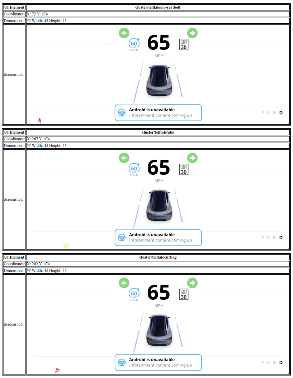
Figure 10. Sample HTML report.
This section describes safety approval tool inputs.
| Input | Short | Type | Description |
|---|---|---|---|
file_path |
-f |
string | File path to human readable report. |
approver_name |
-n |
string | Name of approving engineer. |
approver_email |
-e |
string | Email address of approving engineer. |
output_path |
-o |
string | Destination for generated output. |
This section shows a sample of approval_file.json.
{
    "approver_name": //Name of the approver
    "approver_email": //Email of the approver
    "file_hash": //SHA-256 hash generated against the human readable report.
}
Reference safety monitor
The reference safety monitor is a Rust-based service located in
reference/safety-monitor. The monitor uses the artifacts generated by the
Design Compiler to monitor the state of the system to ensure display safety
compliance.
The monitor runs as a standalone binary (har_safety_monitor) and takes the
path to the data.json file and the base path for artifacts as arguments.
/path/to/har_safety_monitor --data-json-path /path/to/data.json
--artifact-base-path /path/to/artifacts
The monitor performs the following tasks:
- Artifact loading: Loads
data.jsonto identify safety-relevant UI elements and their expected positions and dimensions. - Golden image comparison: Compares the current screen contents with golden images of safety-critical elements generated by the compiler.
- Vehicle data integration: Connects to vehicle data sources to determine the expected state of each telltale.
- Mismatch detection: Logs an error if there is a mismatch between what is expected based on vehicle data and what is visible on screen.
The safety monitor is designed to be built and deployed as part of the system image, typically within a dedicated APEX.