
Many SoC vendors and ODMs support the use of multiple device trees (DTs) on a device, enabling one image to power multiple SKUs or configurations. In such cases, the bootloader identifies the hardware and loads the corresponding DT at runtime:
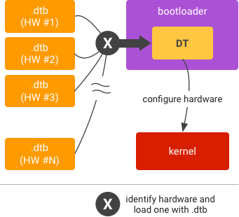
Figure 1. Multiple device tree overlays (DTOs) in bootloader.
Note: Using multiple DTs isn't mandatory.
Set up
To add support for multiple DTs to the DTO model, set up a list of main DTs and another list of overlay DTs.
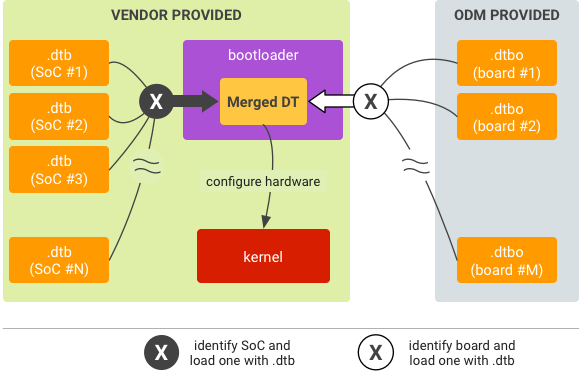
Figure 2. Runtime DTO implementation for multiple DTs.
The bootloader should be able to:
- Read the SoC ID and select the corresponding main DT.
- Read the board ID and select the set of overlay DTs accordingly.
Only one main DT should be selected for use at runtime. Multiple overlay DTs may be selected but they must be compatible with the chosen main DT. Using multiple overlays can help avoid storing one overlay per board within the DTBO partition and enable the bootloader to determine the subset of required overlays based on the board ID (or possibly by probing the peripherals). For example, Board A may need the devices added by the overlays 1, 3, and 5 while Board B may need the devices added by the overlays 1, 4, and 5.
Partition
To partition, determine a bootloader runtime-accessible and trusted location
in flash memory to store the DTBs and DTBOs (bootloader must be able to locate
these files in the matching process). Keep in mind that DTBs and DTBOs cann't
exist in the same partition. If your DTBs/DTBOs are in the
dtb/dtbo partition, use the table structure and header
format detailed in DTB and DTBO
partition format.
Run in bootloader
To run:
- Identify the SoC and load the corresponding .dtb from storage into memory.
- Identify the board and load the corresponding
.dtbofrom storage into memory. - Overlay the
.dtbwith the.dtboto be a merged DT. - Start kernel given the memory address of the merged DT.