
Android provides a reference implementation of all the components needed to implement the Android Virtualization Framework. Currently this implementation is limited to ARM64. This page explains the framework architecture.
Background
The Arm architecture allows up to four exception levels, with exception level 0 (EL0) being the least privileged, and exception level 3 (EL3) the most. The largest portion of the Android codebase (all userspace components) runs at EL0. The rest of what is commonly called "Android" is the Linux kernel, which runs at EL1.
The EL2 layer allows the introduction of a hypervisor that enables isolating memory and devices into individual pVMs at EL1/EL0, with strong confidentiality and integrity guarantees.
Hypervisor
The protected kernel-based virtual machine (pKVM) is built upon the Linux KVM hypervisor, which has been extended with the ability to restrict access to the payloads running in guest virtual machines marked ‘protected’ at the time of creation.
KVM/arm64 supports different execution modes depending on the availability of
certain CPU features, namely, the Virtualization Host Extensions (VHE) (ARMv8.1
and later). In one of those modes, commonly known as the non-VHE mode, the
hypervisor code is split out of the kernel image during boot and installed at
EL2, whereas the kernel itself runs at EL1. Although part of the
Linux codebase, the EL2 component of KVM is a small component in charge of
the switch between multiple EL1s. The hypervisor component is compiled with
Linux, but resides in a separate, dedicated memory section of the vmlinux
image. pKVM leverages this design by extending the hypervisor code with new
features allowing it to put restrictions on the Android host kernel and user
space, and limiting host access to guest memory and the hypervisor.
pKVM vendor modules
A pKVM vendor module is a hardware-specific module containing device-specific functionality, such as input-output memory management unit (IOMMU) drivers. These modules let you port security features requiring exception level 2 (EL2) access to pKVM.
To learn how to implement and load a pKVM vendor module, refer to Implement a pKVM vendor module.
Boot procedure
The following figure depicts the pKVM boot procedure:
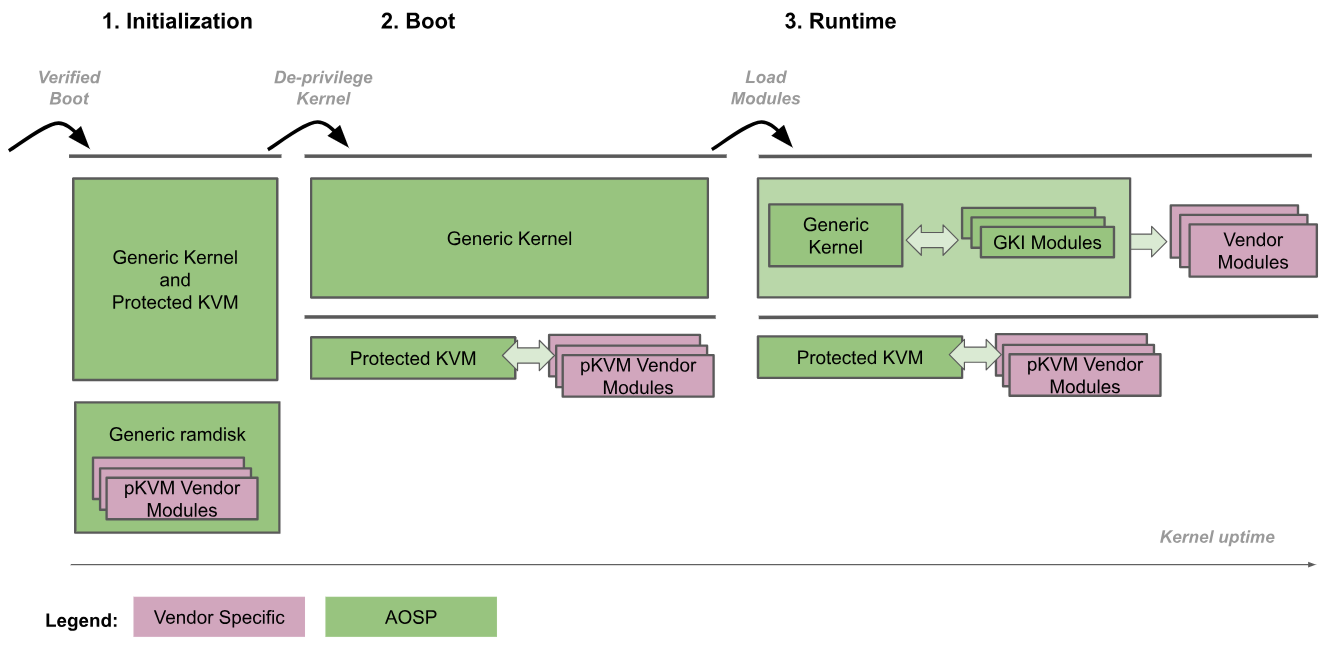
- Initialization: The bootloader enters the generic kernel at EL2. Trusted kernel code at both EL2 and EL1 then initializes pKVM and its modules. During this phase, EL1 is trusted by EL2 so no untrusted code is executed.
- Deprivilege Kernel: The generic kernel detects that it's running at EL2 and deprivileges itself to EL1. pKVM and its modules continue to run at EL2.
- Runtime: The generic kernel proceeds to boot normally, loading all necessary device drivers until reaching user space. At this point, pKVM is in place and handles the stage-2 page tables.
The boot procedure trusts the bootloader to verify and maintain the integrity of the kernel image for the initialization phase. After the kernel is deprivileged, it's no longer considered trusted by the hypervisor, which is then responsible for protecting itself even if the kernel is compromised.
Having the Android kernel and the hypervisor in the same binary image allows for a very tightly coupled communication interface between them. This tight coupling guarantees atomic updates of the two components, which avoids the need to keep the interface between them stable, and offers a great deal of flexibility without compromising long-term maintainability. The tight coupling also allows performance optimizations when both components can cooperate without impacting the security guarantees provided by the hypervisor.
Moreover, the adoption of GKI in the Android ecosystem automatically allows the pKVM hypervisor to be deployed to Android devices in the same binary as the kernel.
CPU memory access protection
The Arm architecture specifies a memory management unit (MMU) split in two independent stages, both of which can be used to implement address translation and access control to different parts of memory. The stage 1 MMU is controlled by EL1 and allows a first level of address translation. The stage 1 MMU is used by Linux to manage the virtual address space provided to each userspace process and to its own virtual address space.
The stage 2 MMU is controlled by EL2 and enables the application of a second address translation on the output address of the stage 1 MMU, resulting in a physical address (PA). The stage 2 translation can be used by hypervisors to control and translate memory accesses from all guest VMs. As shown in figure 2, when both stages of translation are enabled, the output address of the stage 1 is called an intermediate physical address (IPA) Note: The virtual address (VA) is translated into an IPA and then to a PA.
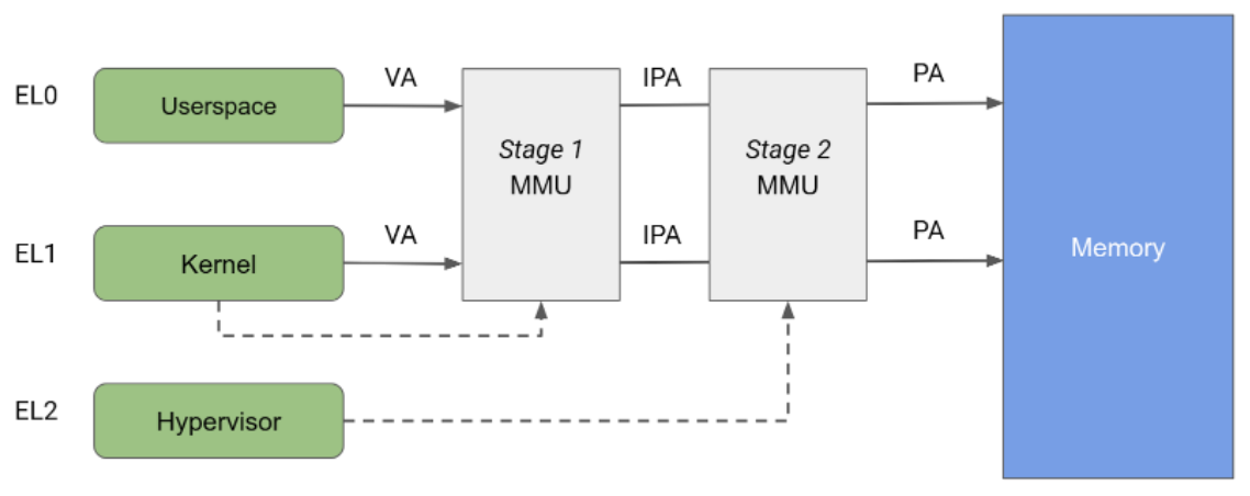
Historically, KVM runs with stage 2 translation enabled while running guests and with stage 2 disabled while running the host Linux kernel. This architecture allows memory accesses from the host stage 1 MMU to pass through the stage 2 MMU, hence allowing unrestricted access from the host to guest memory pages. On the other hand, pKVM enables stage 2 protection even in host context, and puts the hypervisor in charge of protecting guest memory pages instead of the host.
KVM makes full use of address translation at stage 2 to implement complex IPA/PA mappings for guests, which creates the illusion of contiguous memory for guests despite physical fragmentation. However, the usage of the stage 2 MMU for the host is restricted to access control only. The host stage 2 is identity-mapped, ensuring that contiguous memory in the host IPA space is contiguous in the PA space. This architecture allows the use of large mappings in the page table and consequently reduces pressure on the translation lookaside buffer (TLB). Because an identity mapping can be indexed by PA, the host stage 2 is also used to track page ownership directly in the page table.
Direct memory access (DMA) protection
As described previously, unmapping guest pages from the Linux host in the CPU page tables is a necessary but insufficient step for protecting guest memory. pKVM also needs to protect against memory accesses made by DMA-capable devices under the host kernel’s control, and the possibility of a DMA attack initiated by a malicious host. To prevent such a device from accessing guest memory, pKVM requires input-output memory management unit (IOMMU) hardware for every DMA-capable device in the system, as shown in figure 3.
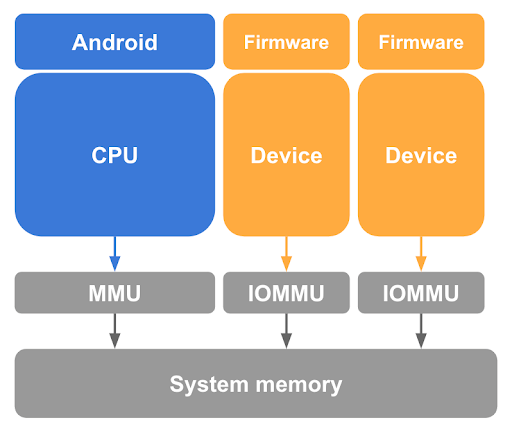
At a minimum, IOMMU hardware provides the means of granting and revoking read/write access for a device to physical memory at page granularity. However, this IOMMU hardware limits the use of devices in pVMs as they assume an identity-mapped stage 2.
To ensure isolation between virtual machines, memory transactions generated on behalf of different entities must be distinguishable by the IOMMU so that the appropriate set of page tables can be used for the translation.
In addition, reducing the amount of SoC-specific code at EL2 is a key strategy to reduce the overall trusted computing base (TCB) of pKVM and runs counter to the inclusion of IOMMU drivers in the hypervisor. To mitigate this issue, the host at EL1 is responsible for auxiliary IOMMU management tasks, such as power management, initialization and, where appropriate, interrupt handling.
However, putting the host in control of the device state places additional requirements on the programming interface of the IOMMU hardware to ensure that permission checks can't be bypassed by other means, for example, following a device reset.
A standard and well supported IOMMU for Arm devices that makes both isolation and direct assignment possible is the Arm System Memory Management Unit (SMMU) architecture. This architecture is the recommended reference solution.
Memory ownership
At boot time, all non-hypervisor memory is assumed to be owned by the host, and is tracked as such by the hypervisor. When a pVM is spawned, the host donates memory pages to allow it to boot and the hypervisor transitions the ownership of those pages from the host to the pVM. Thus, the hypervisor puts access-control restrictions in place in the host’s stage 2 page table to prevent it from accessing the pages again, providing confidentiality to the guest.
Communication between the host and guests is made possible by controlled memory sharing between them. Guests are allowed to share some of their pages back with the host using a hypercall, which instructs the hypervisor to remap those pages in the host stage 2 page table. Similarly, the host’s communication with TrustZone is made possible by memory sharing and/or lending operations, all of which are closely monitored and controlled by pKVM using the Firmware Framework for Arm (FF-A) specification.
Since a pVM's memory requirements can change over time, a hypercall is provided which allows ownership of specified pages belonging to the caller to be relinquished back to the host. In practice this hypercall is used with the virtio balloon protocol to allow the VMM to request memory back from the pVM, and for the pVM to notify the VMM of relinquished pages, in a controlled manner.
The hypervisor is responsible for tracking ownership of all memory pages in the system and whether they're being shared or lent to other entities. Most of this state tracking is done using metadata attached to the host and guests’ stage 2 page tables, using reserved bits in the page table entries (PTEs) which, as their name suggests, are reserved for software use.
The host must ensure that it doesn’t attempt to access pages that have been made inaccessible by the hypervisor. An illegal host access causes a synchronous exception to be injected into the host by the hypervisor, which can either result in the responsible userspace task receiving a SEGV signal, or the host kernel crashing. To prevent accidental accesses, pages donated to guests are made ineligible for swapping or merging by the host kernel.
Interrupt handling and timers
Interrupts are an essential part of the way a guest interacts with devices and for communication between CPUs, where interprocessor interrupts (IPIs) are the main communication mechanism. The KVM model is to delegate all the virtual interrupt management to the host in EL1, which for that purpose behaves as an untrusted part of the hypervisor.
pKVM offers a full Generic Interrupt Controller version 3 (GICv3) emulation based on the existing KVM code. Timer and IPIs are handled as part of this untrusted emulation code.
GICv3 support
The interface between EL1 and EL2 must ensure that the full interrupt state is visible to the EL1 host, including copies of the hypervisor registers related to interrupts. This visibility is typically accomplished using shared memory regions, one per virtual CPU (vCPU).
The system register runtime support code can be simplified to support only the Software Generated Interrupt Register (SGIR) and Deactivate Interrupt Register (DIR) register trapping. The architecture mandates that these registers always trap to EL2, while the other traps have so far only been useful to mitigate errata. Everything else is being handled in hardware.
On the MMIO side, everything is emulated at EL1, reusing all the current infrastructure in KVM. Finally, Wait for Interrupt (WFI) is always relayed to EL1, because this is one of the basic scheduling primitives KVM uses.
Timer support
The comparator value for the virtual timer must be exposed to EL1 on each trapping WFI so that EL1 can inject timer interrupts while the vCPU is blocked. The physical timer is entirely emulated, and all traps relayed to EL1.
MMIO handling
To communicate with the virtual machine monitor (VMM) and perform GIC emulation, MMIO traps must be relayed back to the host in EL1 for further triaging. pKVM requires the following:
- IPA and size of the access
- Data in case of a write
- Endianness of the CPU at the point of trapping
Additionally, traps with a general purpose register (GPR) as a source/destination are relayed using an abstract transfer pseudo-register.
Guest interfaces
A guest can communicate with a protected guest using a combination of hypercalls and memory access to trapped regions. Hypercalls are exposed according to the SMCCC standard, with a range reserved for a vendor allocation by KVM. The following hypercalls are of particular importance to pKVM guests.
Generic hypercalls
- PSCI provides a standard mechanism for the guest to control the lifecycle of its vCPUs including onlining, offlining, and system shutdown.
- TRNG provides a standard mechanism for the guest to request entropy from the pKVM which relays the call to EL3. This mechanism is particularly useful where the host can't be trusted to virtualize a hardware random number generator (RNG).
pKVM hypercalls
- Memory sharing with the host. All guest memory is initially inaccessible to the host, but host access is necessary for shared-memory communication and for paravirtualized devices that rely on shared buffers. Hypercalls for sharing and unsharing pages with the host allow the guest to decide exactly what parts of memory are made accessible to the rest of Android without the need for a handshake.
- Memory relinquishment to the host. All guest memory usually belongs to
the guest until it is destroyed. This state can be inadequate for long-lived
VMs with memory requirements which vary over time. The
relinquishhypercall allows a guest to explicitly transfer ownership of pages back to the host without requiring guest termination. - Memory access trapping to the host. Traditionally, if a KVM guest accesses an address that doesn't correspond to a valid memory region, then the vCPU thread exits to the host and the access is typically used for MMIO and emulated by the VMM in user space. To facilitate this handling, pKVM is required to advertise details about the faulting instruction such as its address, register parameters and potentially their contents back to the host, which could unintentionally expose sensitive data from a protected guest if the trap was not anticipated. pKVM solves this problem by treating these faults as fatal unless the guest has previously issued a hypercall to identify the faulting IPA range as one for which accesses are permitted to trap back to the host. This solution is referred to as the MMIO guard.
Virtual I/O device (virtio)
Virtio is a popular, portable, and mature standard for implementing and interacting with paravirtualized devices. The majority of devices exposed to protected guests are implemented using virtio. Virtio also underpins the vsock implementation used for communication between a protected guest and the rest of Android.
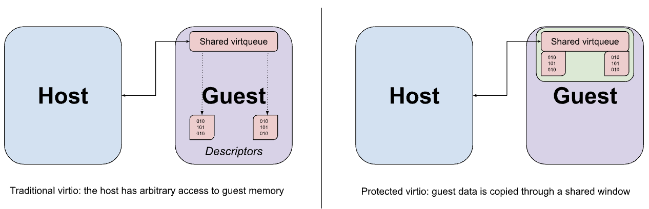
Virtio devices are typically implemented in the host’s user space by the VMM, which intercepts trapped memory accesses from the guest to the MMIO interface of the virtio device and emulates the expected behavior. MMIO access is relatively expensive because each access to the device requires a round-trip to the VMM and back, so most of the actual data transfer between the device and guest occurs using a set of virtqueues in memory. A key assumption of virtio is that the host can access guest memory arbitrarily. This assumption is evident in the design of the virtqueue, which might contain pointers to buffers in the guest that the device emulation is intended to access directly.
Although the previously described memory sharing hypercalls could be used to share virtio data buffers from the guest to the host, this sharing is necessarily performed at page granularity and could end up exposing more data than required if the buffer size is less than that of a page. Instead, the guest is configured to allocate both the virtqueues and their corresponding data buffers from a fixed window of shared memory, with data being copied (bounced) to and from the window as required.
Interaction with TrustZone
Although guests aren't able to interact directly with TrustZone, the host must still be able to issue SMC calls into the secure world. These calls can specify physically addressed memory buffers that are inaccessible to the host. Because the secure software is generally unaware of the accessibility of the buffer, a malicious host could use this buffer to perform a confused deputy attack (analogous to a DMA attack). To prevent such attacks, pKVM traps all host SMC calls to EL2 and acts as a proxy between the host and the secure monitor at EL3.
PSCI calls from the host are forwarded to the EL3 firmware with minimal modifications. Specifically, the entry point for a CPU coming online or resuming from suspend is rewritten so that the stage 2 page table is installed at EL2 before returning to the host at EL1. During boot, this protection is enforced by pKVM.
This architecture relies on the SoC supporting PSCI, preferably through the use of an up-to-date version of TF-A as its EL3 firmware.
Firmware Framework for Arm (FF-A) standardizes interactions between the normal and secure worlds, particularly in the presence of a secure hypervisor. A major part of the specification defines a mechanism for sharing memory with the secure world, using both a common message format and a well-defined permissions model for the underlying pages. pKVM proxies FF-A messages to ensure that the host isn't attempting to share memory with the secure-side for which it doesn't have sufficient permissions.
This architecture relies on the secure world software enforcing the memory access model, to ensure that trusted apps and any other software running in the secure world can access memory only if it's either exclusively owned by the secure world or has been explicitly shared with it using FF-A. On a system with S-EL2, enforcing the memory access model should be done by a Secure Partition Manager Core (SPMC), such as Hafnium, which maintains stage 2 page tables for the secure world. On a system without S-EL2, the TEE can instead enforce a memory access model through its stage 1 page tables.
If the SMC call to EL2 isn't a PSCI call or FF-A defined message, unhandled SMCs are forwarded to EL3. The assumption is that the (necessarily trusted) secure firmware can handle unhandled SMCs safely because the firmware understands the precautions needed to maintain pVM isolation.
Virtual machine monitor
crosvm is a virtual machine monitor (VMM) which runs virtual machines through Linux's KVM interface. What makes crosvm unique is its focus on safety with the use of the Rust programming language and a sandbox around virtual devices to protect the host kernel. For more about crosvm, see its official documentation here.
File descriptors and ioctls
KVM exposes the /dev/kvm character device to userspace with ioctls that make
up the KVM API. The ioctls belong to the following categories:
- System ioctls query and set global attributes that affect the whole KVM subsystem, and create pVMs.
- VM ioctls query and set attributes that create virtual CPUs (vCPUs) and devices, and affect an entire pVM, such as including memory layout and the number of virtual CPUs (vCPUs) and devices.
- vCPU ioctls query and set attributes that control the operation of a single virtual CPU.
- Device ioctls query and set attributes that control the operation of a single virtual device.
Each crosvm process runs exactly one instance of a virtual machine. This process
uses the KVM_CREATE_VM system ioctl to create a VM file descriptor that can
be used to issue pVM ioctls. A KVM_CREATE_VCPU or KVM_CREATE_DEVICE ioctl
on a VM FD creates a vCPU/device and returns a file descriptor pointing to the
new resource. ioctls on a vCPU or device FD can be used to control the device
that was created using the ioctl on a VM FD. For vCPUs, this includes the
important task of running guest code.
Internally, crosvm registers the VM’s file descriptors with the kernel using
the edge-triggered epoll interface. The kernel then notifies crosvm whenever
there's a new event pending in any of the file descriptors.
pKVM adds a new capability, KVM_CAP_ARM_PROTECTED_VM, which can be used to
get information about the pVM environment and set up protected mode for a VM.
crosvm uses this during pVM creation if the --protected-vm flag is passed,
to query and reserve the appropriate amount of memory for
pVM firmware, and then to enable protected mode.
Memory allocation
One of the main responsibilities of a VMM is allocating the VM’s memory and managing its memory layout. crosvm generates a fixed memory layout loosely described in the table below.
| FDT in normal mode | PHYS_MEMORY_END - 0x200000
|
| Free space | ...
|
| Ramdisk | ALIGN_UP(KERNEL_END, 0x1000000)
|
| Kernel | 0x80080000
|
| Bootloader | 0x80200000
|
| FDT in BIOS mode | 0x80000000
|
| Physical memory base | 0x80000000
|
| pVM firmware | 0x7FE00000
|
| Device memory | 0x10000 - 0x40000000
|
Physical memory is allocated with mmap and the memory is donated to the VM to
populate its memory regions, called memslots, with the
KVM_SET_USER_MEMORY_REGION ioctl. All guest pVM memory is therefore
attributed to the crosvm instance that manages it and can result in the
process being killed (terminating the VM) if the host starts running out of
free memory. When a VM is stopped, the memory is automatically wiped by
the hypervisor and returned to the host kernel.
Under regular KVM, the VMM retains access to all guest memory. With pKVM, guest memory is unmapped from the host physical address space when it's donated to the guest. The only exception is memory explicitly shared back by the guest, such as for virtio devices.
MMIO regions in the guest’s address space are left unmapped. Access to these regions by the guest is trapped and results in an I/O event on the VM FD. This mechanism is used to implement virtual devices. In protected mode, the guest must acknowledge that a region of its address space is be used for MMIO using a hypercall, to reduce risk of accidental information leakage.
Scheduling
Each virtual CPU is represented by a POSIX thread and scheduled by the host
Linux scheduler. The thread calls the KVM_RUN ioctl on the vCPU FD, resulting
in the hypervisor switching to the guest vCPU context. The host scheduler
accounts for the time spent in a guest context as time used by the corresponding
vCPU thread. KVM_RUN returns when there's an event that must be handled by
the VMM, such as I/O, end of interrupt, or the vCPU halted. The VMM handles
the event and calls KVM_RUN again.
During KVM_RUN, the thread remains preemptible by the host scheduler, except
for execution of the EL2 hypervisor code, which isn't preemptible. The guest
pVM itself has no mechanism for controlling this behavior.
Because all vCPU threads are scheduled like any other userspace tasks, they're subject to all standard QoS mechanisms. Specifically, each vCPU thread can be affined to physical CPUs, placed in cpusets, boosted or capped using utilization clamping, have their priority/scheduling policy changed, and more.
Virtual devices
crosvm supports a number of devices, including the following:
- virtio-blk for composite disk images, read-only or read-write
- vhost-vsock for communication with the host
- virtio-pci as virtio transport
- pl030 real time clock (RTC)
- 16550a UART for serial communication
pVM firmware
The pVM firmware (pvmfw) is the first code executed by a pVM, similar to the boot ROM of a physical device. pvmfw's primary goal is to bootstrap secure boot and derive the pVM’s unique secret. pvmfw isn't limited to use with any specific OS, such as Microdroid, as long as the OS is supported by crosvm and has been properly signed.
The pvmfw binary is stored in a flash partition of the same name and is updated using OTA.
Device boot
The following sequence of steps is added to the boot procedure of a pKVM-enabled device:
- The Android Bootloader (ABL) loads pvmfw from its partition into memory and verifies the image.
- The ABL obtains its Device Identifier Composition Engine (DICE) secrets (Compound Device Identifiers (CDIs) and DICE certificate chain) from a Root of Trust.
- The ABL derives the necessary CDIs for pvmfw, and appends them to the pvmfw binary.
- The ABL adds a
linux,pkvm-guest-firmware-memoryreserved memory region node to the DT, describing the location and size of the pvmfw binary and the secrets it derived in the previous step. - The ABL hands control over to Linux and Linux initializes pKVM.
- pKVM unmaps pvmfw memory region from host’s stage 2 page tables and protects it from the host (and guests) throughout device uptime.
After device boot, Microdroid is booted per the steps in the Boot sequence section of the Microdroid document.
pVM boot
When creating a pVM, crosvm (or another VMM) must create a sufficiently large memslot to be populated with the pvmfw image by the hypervisor. The VMM is also restricted in the list of registers whose initial value it can set (x0-x14 for the primary vCPU, none for secondary vCPUs). The remaining registers are reserved and are part of the hypervisor-pvmfw ABI.
When the pVM is run, the hypervisor first hands control of the primary vCPU
over to pvmfw. The firmware expects crosvm to have loaded an AVB-signed kernel,
which can be a bootloader or any other image, and an unsigned FDT to memory at
known offsets. pvmfw validates the AVB signature and, if successful,
generates a trusted device tree from the received FDT, wipes its secrets from
memory, and branches to the entry point of the payload. If one of the
verification steps fails, the firmware issues a PSCI SYSTEM_RESET hypercall.
Between boots, information about the pVM instance is stored in a partition (virtio-blk device) and encrypted with pvmfw's secret to ensure that, following a reboot, the secret is being provisioned to the correct instance.