
Implementing device tree overlays (DTOs) involves dividing the device tree (DT), building, partitioning, and running. After you have a working implementation, you must also maintain compatibility between the two DTs and determine a strategy for ensuring the security of each DT partition.
Divide the DT
Start by dividing the DT into two parts:
- Main DT. The SoC-only part and the default configurations, provided by SoC vendor.
- Overlay DT. The device-specific configurations, provided by ODM/OEM.
After dividing the DTs, you must ensure compatibility between main DT and overlay DT so that merging main DT and overlay DT results in a complete DT for the device. For details on DTO format and rules, see DTO syntax. For details on multiple DTs, see Use multiple DTs.
Build main and overlay DTs
To build the main DT:
- Compile the main DT
.dtsinto a.dtbfile. - Flash the
.dtbfile into a bootloader runtime-accessible partition (detailed in [Partition DTs](#partition)).
To build the overlay DT:
- Compile the overlay DT
.dtsinto a.dtbofile. While this file format is the same as the.dtbfile formatted as a flattened DT, the different file extension distinguishes it from the main DT. - Flash the
.dtbofile into a bootloader runtime-accessible partition (detailed in [Partition DTs](#partition)).
For details on compiling with DTC and verifying DTO results on the host, see Compile and verify.
Partition DTs
Determine a bootloader runtime-accessible and trusted location in flash
memory to put .dtb and .dtbo.
Example locations for the main DT:
- Part of boot partition, appended to the kernel (
image.gz) - Separate DT blobs (
.dtb) in dedicated partition (dtb)
Example locations for the overlay DT:
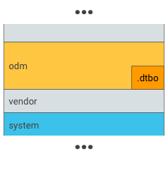
Figure 1. Put .dtbo into an odm partition (do this only if your bootloader has the capability to load data from the filesystem of an odm partition).
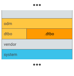
Figure 2. Put .dtbo into a unique partition, such as a dtbo partition.
Note: The size of the overlay DT partition depends on the device and the amount of changes needed on top of the main DT blob. Typically, 8 MB is more than enough and allows room to grow in the future if required.
For devices that support seamless (A/B) updates, A/B the main DT and overlay DT partitions:
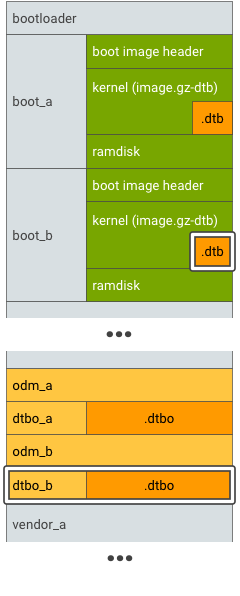
Figure 3. DTBO partition A/B, example 1.
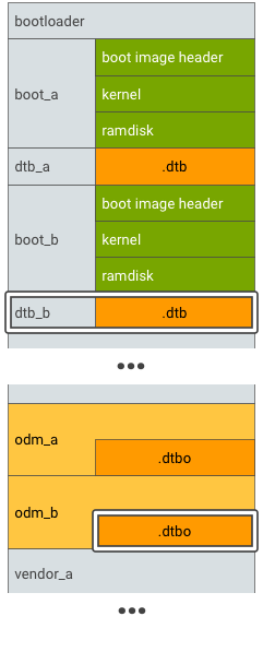
Figure 4. DTBO partition A/B, example 2.
Run in bootloader
To run:
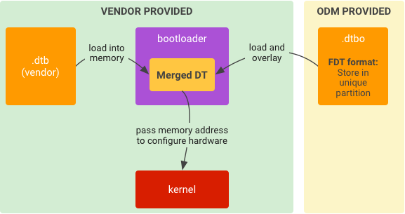
Figure 5. Typical runtime implementation for DTO in bootloader.
- Load
.dtbfrom storage into memory. - Load
.dtbofrom storage into memory. - Overlay
.dtbwith.dtboto be a merged DT. - Start kernel given the memory address of the merged DT.
Maintain compatibility
The main DTB (from SoC vendor) is treated as an API surface for DTBOs. After separating the DT into a SoC-common part and a device-specific part, you must keep the two parts mutually compatible in the future, including:
- DT definition in main DT. For example, nodes, properties, labels. Any definition change in main DT could trigger changes in overlay DT. For example, to correct a node name in main DT, define an "alias" label that maps to the original node name (to avoid the change of overlay DT).
- Overlay DT store location. For example, partition name, store format.
Ensure security
Bootloader must ensure the DTB or DTBO is secure, unmodified, and uncorrupted. You could use any solution to secure DTB or DTBO, for example, Boot image signature in VBoot 1.0 or AVB HASH footer (VBoot 2.0).
- If DTB or DTBO is in a unique partition, you can add that partition to the trust chain of AVB. The trust chain starts from a hardware-protected root of trust and goes to the bootloader, which verifies the integrity and authenticity of DTB or DTBO partition.
- If DTB or DTBO is in an existing partition (such as the
odmpartition), that partition should be in the trust chain of AVB. (DTBO partition could share a public key withodmpartition).
For details, refer to Verified Boot.