Implement haptics

Device manufacturers are generally considered the owners of the private assets created for each device. As such, their engineering efforts are often focused on a per-device basis; little to no effort goes to the consistency of other devices in the ecosystem.

In direct contrast, developers strive to build apps that work on all Android phones in the ecosystem, regardless of each device's technical specifications. This difference in approach can cause a fragmentation problem, for example, the hardware capabilities of certain phones don't match expectations set by the app developers. So if the haptics APIs work on some Android phones but not others, the result is an inconsistent ecosystem. This is why hardware configuration plays a critical role in ensuring that manufacturers can implement Android haptics APIs on every device.

This page provides a step-by-step checklist to set up hardware compliance for the best use of the Android haptics APIs.

The following figure illustrates building common knowledge between device manufacturers and developers, which is a critical step in creating a cohesive ecosystem:
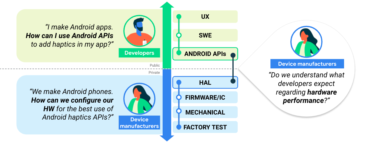
Diagram of haptics use cases for app developers and device
manufacturers

Figure 1. Building knowledge between device manufacturers and developers

Haptics implementation checklist

  1. Implement constants

    • List of constants to implement haptics.
  2. Implement primitives

    • Implementation guidance for HAL composition primitives.
  3. Map constants between HAL and API

  4. Assess the hardware

    • Instructions on target haptic effects. Use these instructions to perform quick checks on your hardware.

We'll explore each of these steps in greater detail below.

Step 1: Implement constants

Perform these checks to determine if your device meets the minimum requirements to implement haptics:

Flowchart of the haptics implementation
process

Figure 2. Implementing effects

Flowchart of steps for implementing
primitives

Figure 3. Implementing primitives

Check the implementation status of the following haptic constants.

Haptic constants Locations and summaries
EFFECT_TICK, EFFECT_CLICK, EFFECT_HEAVY_CLICK, EFFECT_DOUBLE_CLICK VibrationEffect class
Haptic constants in VibrationEffect don't include any notion of input events, and have no UI elements. Constants include the notion of energy levels instead, such as EFFECT_CLICK and EFFECT_HEAVY_CLICK, which are called by createPredefined().

The alternative vibrations described below are performed on devices that don't implement the VibrationEffect constants. Updating these configurations to perform best on such devices is recommended.

  • EFFECT_CLICK

    Waveform vibration created with VibrationEffect.createWaveform and the timings configured at frameworks/base/core/res/res/values/config.xml##config_virtualKeyVibePattern.

  • EFFECT_HEAVY_CLICK

    Waveform vibration created with VibrationEffect.createWaveform and the timings configured at frameworks/base/core/res/res/values/config.xml##config_longPressVibePattern.

    • EFFECT_DOUBLE_CLICK

    Waveform vibration created with VibrationEffect.createWaveform and the timings (0, 30, 100, 30).

  • EFFECT_TICK

    Waveform vibration created with VibrationEffect.createWaveform and the timings configured at frameworks/base/core/res/res/values/config.xml##config_clockTickVibePattern.

Flowchart of steps for testing haptic
feedback

Figure 4. Implementing feedback constants

Check the status of the following public feedback constants.

Haptic constants Locations and summaries
CLOCK_TICK, CONTEXT_CLICK, KEYBOARD_PRESS, KEYBOARD_RELEASE, KEYBOARD_TAP, LONG_PRESS, TEXT_HANDLE_MOVE, VIRTUAL_KEY, VIRTUAL_KEY_RELEASE, CONFIRM, REJECT, GESTURE_START, GESTURE_END HapticFeedbackConstants class
Haptic constants in HapticFeedbackConstants assist input events with certain UI elements, such as KEYBOARD_PRESS and KEYBOARD_RELEASE, which are called by performHapticFeedback().

Step 2: Implement primitives

Haptic primitives in VibrationEffect.Composition have scalable intensity that developers can use through addPrimitive(int primitiveId, float scale, int delay). The primitives can be divided into two categories:

  • Short primitives: Primitives with short duration, usually less than 20 ms. These are CLICK, TICK and LOW_TICK.

  • Chirp primitives: Primitives with varying amplitude and frequency, usually with a longer duration than short primitives. These are SLOW_RISE, QUICK_RISE, QUCK_FALL, THUD, and SPIN.

Short primitives

Short primitives can be described by the vibrator motor output acceleration profile. The absolute frequency used varies for each primitive, depending on the actuator's resonant frequency. See Set up the testing equipment for more information about hardware setup and tools for measuring the output.

A valuable quality metric for short vibrations is the pulse to ring ratio (PRR), shown in Figure 5. PRR is defined as the ratio between the main pulse, defined by the signal inside the duration window where the amplitude decreases to 10% of peak amplitude, and the ring pulse, defined by the signal where the amplitude decreases from 10% peak amplitude to less than 1% of the peak amplitude. The formula for PRR is:

$$ \text{Pulse to ring ratio (PRR)} = 20log_{10}\frac{\text{RMS (main pulse)}}{\text{RMS (ring)}} $$

For more information on PRR, see Analyze the waveform and for more information on analyzing and comparing results, see Compare results using the performance map.

Pulse to Ring Ratio

Figure 5. Pulse to ring ratio definition

Apply short primitives as a user input feedback or played in longer compositions to create soft textures. This means that they are usually triggered frequently and played in quick succession. The perceived intensity of a single short primitive can compound the larger effect intensity. For this reason, calibrate a single tick or low tick primitive with a larger composition, for example, 100 consecutive ticks.

Click primitive

The click primitive is a strong, crisp effect usually operating close to a device's resonant frequency to reach maximum output in a short duration. It's stronger and deeper than the other primitives, performing at maximum intensity.

If available, use motor overdrive at the beginning and active braking at the end to achieve a short motor rise and fall time. For some motors, using a square wave instead of sine wave can achieve faster acceleration. Figure 6 shows an example output acceleration profile for the click primitive:

Click primitive output acceleration profile

Figure 6. Example of output acceleration profile for click primitive

Parameter Guideline
Duration

Target: 12 ms

Limit: < 30 ms

Peak output acceleration

Target: 2 G

Limit: > 1 G

Frequency Roughly at resonant frequency

Tick primitive (light tick)

The tick primitive is a sharp, short effect usually operating at a higher frequency range. This primitive can also be described as a medium intensity click at a higher frequency with a short tail. The same guidance applies for achieving a short rise time using motor overdrive or a square wave for the initial onset, and active braking at offset. Figure 7 shows an example output acceleration profile for the tick primitive:

Tick primitive output acceleration profile

Figure 7. Example of output acceleration profile for tick primitive

Parameter Guideline
Duration

Target: 5 ms

Limit: < 20 ms

Peak output acceleration

Target: Half of CLICK, 1 G

Limit: Between 0.5 G and 1 G

Frequency

Target: 2x resonant frequency

Limit: < 500 Hz

Low tick primitive

The low tick primitive is a softer, weaker version of a light tick, operating at a lower frequency range to provide more body to the effect. This primitive can also be described as a medium intensity click at a lower frequency, intended to be used repetitively for dynamic feedback. The same guidance applies for achieving a short rise time using motor overdrive or a square wave for the initial onset. Figure 8 shows an example output acceleration profile for the low tick primitive:

Low tick primitive output acceleration profile

Figure 8. Example of output acceleration profile for low tick primitive

Parameter Guideline
Duration

Target: 12 ms

Limit: < 30 ms

Peak output acceleration

Target: 1/4 of a TICK, 0.25 G

Limit: Between 0.2 G and 0.5 G

Frequency

Target: 2/3 resonant frequency

Limit: < 100 Hz

Chirp primitives

Chirp primitives can be described by the input signals for voltage level and vibration frequency. The acceleration that the motor is able to output at different frequency ranges varies depending on the frequency response curve of the actuator. The frequency ranges and voltage levels need to be adjusted on a per device basis.

Slow rise primitive

The slow rise is a slow amplitude and frequency sweep upward with soft onset and consistently increasing vibration intensity across the sweep. It can be implemented by a consistent sweep of both the amplitude and frequency, using a lower frequency range that operates off resonance. Figure 9 shows the input parameters and an example output acceleration profile for this implementation. (The red line matches the amplitude labels on the left and represent how the vibration amplitude varies with time. The blue line matches the frequency labels on the right and represent how vibration frequency varies with time.)

Input parameters and output acceleration profile for slow rise primitive

Figure 9. Input parameters and example of output acceleration profile for slow rise primitive

If the frequency response of the motor is limited (not strong enough off of its resonant frequency) then an alternative implementation is a sine sweep from 1/2x to 1x the resonant frequency. The motor resonance contributes to reaching the signal peak at the end.

Parameter Guideline
Duration

Target: 500 ms

Tolerance: 20 ms

Peak output acceleration

Target: 0.5 G

Limit: Between 0.5 G and 1 G

Frequency

Target: 1/2 to 2/3 of resonant frequency

Alternative: 1/2 to resonant frequency

Quick rise primitive

The quick rise is a faster amplitude and frequency sweep upward with soft onset and consistently increasing vibration intensity across the sweep. The output acceleration and vibration frequency targets should be the same as the slow rise primitive, achieved in a shorter duration. Figure 10 shows the vibration input parameters and an example output acceleration profile for the slow rise primitive. (The red line matches the amplitude labels on the left and represent how the vibration amplitude varies with time. The blue line matches the frequency labels on the right and represent how vibration frequency varies with time.)

Input parameters and output acceleration profile for quick rise primitive

Figure 10. Input parameters and example of output acceleration profile for quick rise primitive

Parameter Guideline
Duration

Target: 150 ms

Tolerance: 20 ms

Peak output acceleration

Target: Same as SLOW_RISE

Limit: Same as SLOW_RISE

Frequency

Target: Same as SLOW_RISE

Alternative: Same as SLOW_RISE

Quick fall primitive

The quick fall is a fast amplitude and frequency downward sweep with a soft onset. You can use a higher frequency as the start point while the motor is ramping up to reach the peak output acceleration. The frequency should be consistently decreasing across the sweep, even during the rise time. Figure 11 shows the input parameters and an example output acceleration profile for this implementation. (The red line matches the amplitude labels on the left and represent how the vibration amplitude varies with time. The blue line matches the frequency labels on the right and represent how vibration frequency varies with time.)

Input parameters and output acceleration profile for quick fall primitive

Figure 11. Input parameters and example of output acceleration profile for quick fall primitive

Parameter Guideline
Duration

Target: 100 ms

Tolerance: 20 ms

Peak output acceleration

Target: 1 G

Limit: Between 0.5 G and 2 G

Frequency

Target: 2x to 1x the resonant frequency

Thud primitive

The thud is a thumpy, low, percussive effect that simulates the physical sensation of knocking on hollow wood. This primitive operates in a low frequency range, similar to the low tick primitive, to provide more body to the effect. You can implement the thud primitive as an amplitude and frequency downward sweep at a lower frequency range (preferably less than 100 Hz). Figure 12 shows the input parameters and an example output acceleration profile for this implementation. (The red line matches the amplitude labels on the left and represent how the vibration amplitude varies with time. The blue line matches the frequency labels on the right and represent how vibration frequency varies with time.)

Input parameters and output acceleration profile for thud primitive

Figure 12. Input parameters and example of output acceleration profile for thud primitive

If the frequency response of the motor is limited then an alternative implementation is to start with a full intensity drive signal at the resonant frequency and drop to the lowest possible frequency that can still be perceived. This approach might require an increase of the drive signal intensity at the lower frequency for vibration to be felt.

Parameter Guideline
Duration

Target: 300 ms

Tolerance: 20 ms

Peak output acceleration

Target: 0.25 G

Limit: Between 0.2 G and 0.5 G

Frequency

Target: 1/2 to 1/3 of resonant frequency

Alternative: 1x to 1/2 of resonant frequency

Spin primitive

The spin simulates a spinning momentum of fast up and down spin with a slight accent at the center. The spin can be implemented by sweeping the amplitude and frequency independently, in opposite directions and followed by the reverse motion. It's important to use a lower frequency range (preferably less than 100 Hz). Figure 13 shows the input parameters and an example output acceleration profile for this implementation. (The red line matches the amplitude labels on the left and represent how the vibration amplitude varies with time. The blue line matches the frequency labels on the right and represent how vibration frequency varies with time.)

We recommended that the spin primitive is called twice in succession, or three times in compositions, to achieve a spinning and unsteady sensation.

If the frequency response of the motor is limited, an alternative implementation is to do a rapid sine sweep from 1/2x to 1x the resonant frequency and back. The motor resonance automatically gives the signal an accent in the middle.

Input parameters and output acceleration profile for spin primitive

Figure 13. Input parameters and example of output acceleration profile for spin primitive

Parameter Guideline
Duration

Target: 150 ms

Tolerance: 20 ms

Peak output acceleration

Target: 0.5 G

Limit: Between 0.25 G and 0.75 G

Frequency

Target: 2/3 to 1/3, then back to 1/2 of resonant frequency

Alternative: 2/3 to 1x, then back to 1/2 of resonant frequency

Step 3: Map constants between HAL and API

Step 3 presents recommended mappings between public HAL constants and API constants. If the hardware assessed in Step 1 doesn't implement the HAL constants, then use Step 3 to update the fallback patterns described in Step 1 in order to generate similar outputs. The mapping is assisted by two different default models:

  • Discrete model (simple)

    • Amplitude is the key variable of this model. Each entity in the HAL represents a different haptic amplitude.
    • This model is a minimum requirement needed to implement the basic haptic UX.
    • A more advanced haptic UX requires advanced hardware and an advanced model (continuous model).
  • Continuous model (advanced)

    • Texture and amplitude are the key variables of this model. Each entity in the HAL represents different haptic textures. The amplitude of each HAL entity is controlled by the scale factor (S).
    • This model requires advanced hardware. If OEMs want to use advanced haptic UX with VibrationEffect.Composition (for the best use of the latest haptics APIs), implementing their hardware using this model is recommended.

Discrete model

Mapping all public constants provided in the API with appropriate HAL constants is recommended. To begin this process, find out how many haptic waveforms with discrete amplitude the device can define in the HAL. A specific question structured around that notion looks like this: How many single-impulse haptic effects with human-perceptible amplitude differences can be defined in my phone? The answer to this question determines the mapping.

Defining HAL constants is a hardware-dependent process. For example, an entry-level phone might have only the hardware capabilities to produce a single haptic waveform. Devices with more advanced hardware components produce a wider range of discrete amplitude levels, and can define multiple haptic waveforms in the HAL. HAL-API constant mapping takes the HAL constant (using the medium amplitude as a baseline), then arranges stronger or weaker effects from there.

Diagram of HAL constant range and feedback
amplitudes

Figure 14. HAL constant range by amplitude

When the number of HAL constants with discrete amplitude is defined, it's time to map HAL and API constants by the number of HAL constants. This mapping process can segment a single impulse API constant into up to three discrete groups of amplitude levels. The way that API constants are segmented is based on UX principles for accompanying input events. For more information, see Haptics UX design.

Discrete model for HAL-API constant
mapping

Figure 15. HAL-API constant mapping: Discrete model

If your device supports only two HAL constants with discrete amplitudes, consider merging Medium and High amplitude level HAL constants. An example of this notion in practice would be mapping EFFECT_CLICK and EFFECT_HEAVY_CLICK to the same HAL constant, which would be the Medium amplitude level HAL constant. If your device supports only one HAL constant with discrete amplitude, consider merging all three levels into one.

Continuous model

The continuous model with amplitude scalability can be applied to define HAL constants. A scale factor (S) can be applied to the HAL constants (for example, HAL_H0, HAL_H1) to produce the scaled HAL (HAL_H0 x S). In this case, the scaled HAL is mapped to define API constants (HAL_H0 x S1 = H0S1 = EFFECT_TICK) as shown in figure 16. By using amplitude scalability of the continuous model, a device can store a small number of HAL constants with distinctive textures and add amplitude variations by adjusting the scale factor (S). Device manufacturers can define the number of HAL constants based on how many different haptic textures they want to provide.

HAL constant range by texture and
amplitude

Figure 16. HAL constant range by texture (HAL_H0) and amplitude scale (S)

Continuous model for HAL-API constant
mapping

Figure 17. HAL-API constant mapping: Continuous model

In the continuous model, different HAL constants represent different haptic textures rather than different amplitudes; the scale factor (S) can configure the amplitude. However, because the perception of the texture (for example, sharpness) is related to the perception of the duration and amplitude, combining the texture and the scale factor (in the design process of HAL-API mapping) is recommended.

Figure 18 illustrates constant mapping by increasing variation from one HAL to many API constants with amplitude scalability.

Increasing Varation
1

Increasing Varation
2

Figure 18. Increasing variation with amplitude scalability

For all scalable API constants such as PRIMITIVE_TICK and PRIMITIVE_CLICK in VibrationEffect.Composition, the energy level of the API constant depends on the float scale parameter when the API constant is declared through addPrimitive(int primitiveID, float scale, int delay). PRIMITIVE_TICK and PRIMITIVE_CLICK can be designed with a clear distinction by using different HAL constants. This approach is recommended if you want to add variation to texture.

Step 4: Assess the hardware

Hardware assessment involves defining three haptic effects, labeled Effects 1, 2, and 3 for this specific assessment.

Effect 1: Predefined short haptic constants

The VibrationEffect.EFFECT_CLICK constant is the baseline effect or common denominator in the HAL-API mapping provided in Step 2. It's mapped with the most used effect, HapticFeedbackConstants.KEYBOARD_PRESS. Assessing this effect helps determine the readiness of your target device for clear haptics.

Effect 2: Short custom haptic effect

The VibrationEffect.createOneShot(20,255) constant is for custom haptic effects. For short, single custom impulses, 20 ms is the recommended maximum threshold to define duration. A single impulse longer than 20 ms isn't recommended because it's perceived as a buzzy vibration.

Waveform of short custom haptic
effect

Figure 19. Short custom haptic effect

Effect 3: Long custom haptic effect with amplitude variation

The VibrationEffect.createWaveform(timings[], amplitudes[], int repeat) constant is for long custom effects with amplitude variation. The ability to produce varying amplitudes for custom haptic effects is one of the indicators to evaluate the device's capabilities for rich haptics. The recommended timings [] and amplitudes [] are {500, 500} and {128, 255}, respectively, which presents an increasing trend of amplitude from 50% to 100%, with a 500 ms sampling rate.

Haptic effect waveform with amplitude
variation

Figure 20. Long custom haptic effect with amplitude variation

To check the hardware capabilities of amplitude control for Effect 3, use the Vibrator.hasAmplitudeControl() method. The result has to be true to execute VibrationEffect.createWaveform with varying amplitude as intended.

Flowchart of subjective haptic effect
assessment

Figure 21. Subject assessment of haptic effect 1, 2, and 3

Perform a subjective assessment

For a quick coherence check, perform a subjective assessment first. The goal of the subjective assessment is to observe the amplitude of the haptic effects to determine whether the device can generate haptics with human-perceptible amplitudes.

A specific question structured around this notion looks like this: Can the device produce perceptible haptic effects to the users as expected? Answering this question helps you avoid failed haptics, including imperceptible haptics that users can't feel, or unintended haptics where waveforms don't produce patterns as intended.

Perform an advanced assessment

Performing advanced quality assessments is highly recommended. Advanced quality assessments characterize quantifiable attributes of haptic effects to implement quality haptics. When finished, device manufacturers should be able to diagnose the current haptic status, which means they can set goals to improve the overall quality. See Hardware assessment.