
يوضّح هذا القسم محاور أدوات الاستشعار وأدوات الاستشعار الأساسية وأدوات الاستشعار المركّبة (النشاط والاتجاه والقيم غير المعدَّلة والتفاعل).
محاور أجهزة الاستشعار
يتم التعبير عن قيم أحداث أجهزة الاستشعار من العديد من أجهزة الاستشعار في إطار محدّد ثابت بالنسبة إلى الجهاز.
محاور الجهاز الجوّال
تكون واجهة برمجة التطبيقات Sensor API مرتبطة فقط بالاتجاه الطبيعي للشاشة (لا يتم تبديل المحاور عند تغيير اتجاه شاشة الجهاز).

الشكل 1. نظام الإحداثيات (بالنسبة إلى جهاز جوّال) الذي تستخدمه Sensor API
محاور السيارات
في عمليات تنفيذ Android Automotive، يتم تحديد المحاور بالنسبة إلى هيكل السيارة. نقطة الأصل في نظام الإحداثيات المرجعي للمركبة هي مركز المحور الخلفي. يتم توجيه إطار مرجع المركبة على النحو التالي:
- يشير المحور X إلى اليمين ويقع على مستوى أفقي، وهو عمودي على مستوى التماثل للمركبة.
- يشير المحور Y إلى الأمام ويقع على مستوى أفقي.
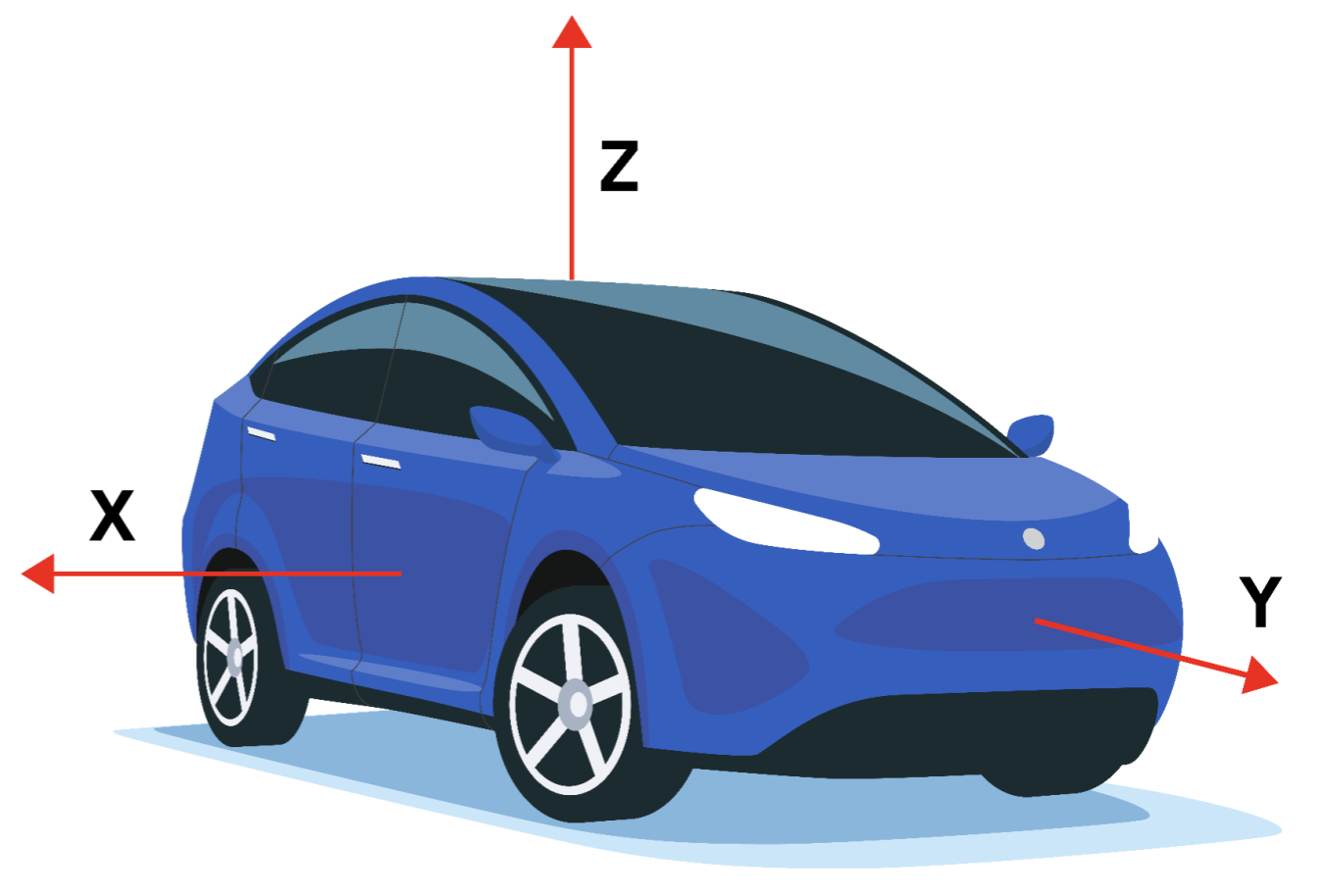
الشكل 2. نظام الإحداثيات (بالنسبة إلى جهاز خاص بالسيارة) الذي تستخدمه Sensor API
إطار مرجع المركبة هو نظام إحداثيات يمنى. لذلك، يشير المحور Z إلى الأعلى.
يكون المحور Z لنظام الإحداثيات المرجعي محاذيًا للجاذبية، ما يعني أنّ المحورين X وY كلاهما أفقيان. نتيجةً لذلك، قد لا يمر المحور Y دائمًا عبر المحور الأمامي.
أجهزة الاستشعار الأساسية
تتم تسمية أنواع أجهزة الاستشعار الأساسية على اسم أجهزة الاستشعار المادية التي تمثّلها. تنقل أجهزة الاستشعار هذه البيانات من جهاز استشعار مادي واحد (على عكس أجهزة الاستشعار المركّبة التي تنشئ البيانات من أجهزة استشعار أخرى). تشمل أمثلة أنواع أجهزة الاستشعار الأساسية ما يلي:
SENSOR_TYPE_ACCELEROMETERSENSOR_TYPE_GYROSCOPESENSOR_TYPE_MAGNETOMETER
ومع ذلك، لا تساوي أجهزة الاستشعار الأساسية أجهزة الاستشعار المادية الأساسية، ويجب عدم الخلط بينهما. إنّ البيانات الواردة من جهاز استشعار أساسي ليست الناتج الأولي لجهاز الاستشعار الفعلي لأنّه يتم تطبيق تصحيحات (مثل تعويض الانحياز وتعويض درجة الحرارة).
على سبيل المثال، قد تختلف خصائص مستشعر أساسي عن خصائص المستشعر المادي الأساسي في حالات الاستخدام التالية:
- شريحة جيروسكوب مصنَّفة بنطاق انحراف يبلغ درجة واحدة في الثانية.
- بعد المعايرة في المصنع، يتم تطبيق تعويض درجة الحرارة وتعويض الانحياز، وسيتم تقليل الانحياز الفعلي لجهاز الاستشعار في Android، وقد يصل إلى حدّ يضمن أن يكون الانحياز أقل من 0.01 درجة/ثانية.
- في هذه الحالة، نقول إنّ جهاز استشعار Android لديه انحياز أقل من 0.01 درجة/ثانية، على الرغم من أنّ ورقة البيانات الخاصة بجهاز الاستشعار الأساسي تشير إلى 1 درجة/ثانية.
- مقياس ضغط جوي يستهلك 100 uW من الطاقة
- وبما أنّه يجب نقل البيانات التي تم إنشاؤها من الشريحة إلى نظام SoC، قد تكون تكلفة الطاقة الفعلية لجمع البيانات من مقياس الضغط الجوي في مستشعر Android أعلى بكثير، مثلاً 1000 ميكروواط.
- في هذه الحالة، نقول إنّ مستشعر Android يستهلك طاقة مقدارها 1000 ميكروواط، على الرغم من أنّ استهلاك الطاقة الذي تم قياسه عند أطراف شريحة مقياس الضغط الجوي يبلغ 100 ميكروواط.
- مقياس مغناطيسي يستهلك 100 ميكروواط عند معايرته، ولكنّه يستهلك المزيد عند إجراء المعايرة.
- قد يتطلّب روتين المعايرة تفعيل الجيروسكوب، ما يستهلك 5,000 ميكروواط، وتشغيل بعض الخوارزميات، ما يستهلك 900 ميكروواط أخرى.
- في هذه الحالة، نقول إنّ الحد الأقصى لاستهلاك الطاقة في مستشعر Android (مقياس المغناطيسية) هو 6000 ميكروواط.
- في هذه الحالة، يكون متوسط استهلاك الطاقة هو المقياس الأكثر فائدة، وهو ما يتم تسجيله في الخصائص الثابتة لجهاز الاستشعار من خلال طبقة HAL.
مقياس التسارع
Reporting-mode: Continuous
getDefaultSensor(SENSOR_TYPE_ACCELEROMETER)
تعرض هذه السمة جهاز استشعار غير مفعّل
يرصد مستشعر مقياس التسارع تسارع الجهاز على طول محاور المستشعر الثلاثة. يتضمّن التسارع المقاس كلاً من التسارع الفيزيائي (تغيير السرعة) والجاذبية. يتم تسجيل القياس في الحقول x وy وz الخاصة بـ sensors_event_t.acceleration.
جميع القيم بوحدات النظام الدولي (م/ث^2) وتقيس تسارع الجهاز مطروحًا منه قوة الجاذبية على طول محاور أجهزة الاستشعار الثلاثة.
إليك بعض الأمثلة:
- يجب أن يكون معيار (س، ص، ع) قريبًا من 0 عند السقوط الحر.
- عندما يكون الجهاز مستويًا على طاولة ويتم دفعه من الجانب الأيسر إلى الجانب الأيمن، تكون قيمة التسارع على المحور x موجبة.
- عندما يكون الجهاز مستويًا على طاولة، تكون قيمة التسارع على طول المحور z هي +9.81 alo، وهو ما يتوافق مع تسارع الجهاز (0 م/ث^2) مطروحًا منه قوة الجاذبية (-9.81 م/ث^2).
- عندما يكون الجهاز مستويًا على طاولة ويتم دفعه نحو السماء، تكون قيمة التسارع أكبر من 9.81+، وهو ما يتوافق مع تسارع الجهاز (+A م/ث^2) مطروحًا منه قوة الجاذبية الأرضية (9.81- م/ث^2).
تتم معايرة القراءات باستخدام:
- تعويض درجة الحرارة
- معايرة التحيز على الإنترنت
- معايرة الميزان على الإنترنت
يجب عدم تعديل معايرة الانحياز والمقياس إلا أثناء إيقاف المستشعر، وذلك لتجنُّب حدوث قفزات في القيم أثناء البث.
يُبلغ مقياس التسارع أيضًا عن مدى دقّة القراءات المتوقّعة من خلال sensors_event_t.acceleration.status. راجِع ثوابت
SensorManager
SENSOR_STATUS_* للحصول على مزيد من المعلومات حول القيم المحتملة لهذا الحقل.
درجة الحرارة المحيطة
Reporting-mode: On-change
getDefaultSensor(SENSOR_TYPE_AMBIENT_TEMPERATURE)
تعرض هذه السمة جهاز استشعار غير مفعّل
توفّر أداة الاستشعار هذه درجة الحرارة المحيطة (في الغرفة) بالدرجة المئوية.
مستشعر المجال المغناطيسي
Reporting-mode: Continuous
getDefaultSensor(SENSOR_TYPE_MAGNETIC_FIELD)
تعرض هذه السمة جهاز استشعار غير مفعّل
SENSOR_TYPE_GEOMAGNETIC_FIELD == SENSOR_TYPE_MAGNETIC_FIELD
تعرض أداة استشعار المجال المغناطيسي (المعروفة أيضًا باسم مقياس المغناطيسية) المجال المغناطيسي المحيط، كما يتم قياسه على طول محاور أداة الاستشعار الثلاثة.
يتم تسجيل القياس في الحقول x وy وz الخاصة بـ
sensors_event_t.magnetic، وتكون جميع القيم بوحدة ميكرو تسلا (uT).
يُبلغ مقياس المغناطيسية أيضًا عن مدى دقة القراءات المتوقّعة من خلال sensors_event_t.magnetic.status. راجِع ثوابت
SensorManager
SENSOR_STATUS_* للحصول على مزيد من المعلومات حول القيم المحتملة لهذا الحقل.
تتم معايرة القراءات باستخدام:
- تعويض درجة الحرارة
- المعايرة في المصنع (أو على الإنترنت) باستخدام الحديد اللين
- المعايرة على الإنترنت
الجيروسكوب
Reporting-mode: Continuous
getDefaultSensor(SENSOR_TYPE_GYROSCOPE)
تعرض هذه السمة جهاز استشعار غير مفعّل
يرصد مستشعر الجيروسكوب معدّل دوران الجهاز حول محاور المستشعر الثلاثة.
تكون قيمة الدوران موجبة في اتجاه عكس عقارب الساعة (قاعدة اليد اليمنى). أي أنّ المراقب الذي ينظر من موقع جغرافي موجب على المحور x أو y أو z إلى جهاز موضوع في نقطة الأصل سيسجّل دورانًا موجبًا إذا بدا أنّ الجهاز يدور في اتجاه معاكس لعقارب الساعة. يُرجى العِلم أنّ هذا هو التعريف الرياضي المعياري للتدوير الموجب، وهو لا يتوافق مع تعريف الميلان في مجال الطيران والفضاء.
يتم عرض القياس في الحقول x وy وz ضمن
sensors_event_t.gyro
وتكون جميع القيم بوحدة راديان في الثانية (rad/s).
تتم معايرة القراءات باستخدام:
- تعويض درجة الحرارة
- التعويضات على نطاق واسع في المصانع (أو على الإنترنت)
- معايرة الانحياز على الإنترنت (لإزالة الانحراف)
يُبلغ الجيروسكوب أيضًا عن مدى دقّة القراءات المتوقّعة من خلال
sensors_event_t.gyro.status. راجِع ثوابت
SensorManager
SENSOR_STATUS_* للحصول على مزيد من المعلومات حول القيم المحتملة لهذا الحقل.
لا يمكن محاكاة الجيروسكوب استنادًا إلى مقاييس المغناطيسية ومقاييس التسارع، لأنّ ذلك سيؤدي إلى انخفاض مستوى التناسق والاستجابة المحليَّين. ويجب أن يستند إلى شريحة جيروسكوب عادية.
معدّل نبضات القلب
Reporting-mode: On-change
getDefaultSensor(SENSOR_TYPE_HEART_RATE)
تعرض هذه السمة جهاز استشعار غير مفعّل
يرصد جهاز استشعار معدّل نبضات القلب معدّل نبضات القلب الحالي للشخص الذي يلمس الجهاز.
يتم عرض معدّل نبضات القلب الحالي بعدد النبضات في الدقيقة (BPM) في
sensors_event_t.heart_rate.bpm، كما يتم عرض حالة جهاز الاستشعار في
sensors_event_t.heart_rate.status. راجِع ثوابت
SensorManager
SENSOR_STATUS_* للحصول على مزيد من المعلومات حول القيم المحتملة لهذا الحقل. على وجه الخصوص، عند التفعيل للمرة الأولى، يجب ضبط حقل الحالة للحدث الأول على SENSOR_STATUS_UNRELIABLE، ما لم يكن معروفًا أنّ الجهاز ليس على الجسم. بما أنّ هذا المستشعر يعمل عند حدوث تغيير، يتم إنشاء الأحداث عند تغيير heart_rate.bpm أو heart_rate.status فقط منذ آخر حدث. لا يتم إنشاء الأحداث بشكل أسرع من كل sampling_period.
يستبدل إطار العمل تلقائيًا sensor_t.requiredPermission بالإذن المناسب للحفاظ على التوافق. يستخدم إطار العمل الإذن
SENSOR_PERMISSION_READ_HEART_RATE للإصدار Android 16 والإصدارات الأحدث، والإذن
SENSOR_PERMISSION_BODY_SENSORS للإصدار Android 15 والإصدارات الأقدم.
فاتح
Reporting-mode: On-change
getDefaultSensor(SENSOR_TYPE_LIGHT)
تعرض هذه السمة جهاز استشعار غير مفعّل
يرصد مستشعر الضوء مستوى الإضاءة الحالي بوحدات لوكس وفقًا للنظام الدولي للوحدات.
يتم تسجيل القياس في sensors_event_t.light.
التقارب
Reporting-mode: On-change
يُعرَّف عادةً على أنّه جهاز استشعار للاستيقاظ
getDefaultSensor(SENSOR_TYPE_PROXIMITY)
تعرض أداة استشعار لتشغيل الكاميرا
تعرض أداة استشعار التقارب المسافة من الأداة إلى أقرب سطح مرئي.
حتى الإصدار 4.4 من نظام التشغيل Android، كانت أجهزة استشعار التقارب تعمل دائمًا كأجهزة استشعار تنبيه، حيث كانت تنبّه نظام التشغيل على الشريحة عند رصد تغيير في التقارب. بعد الإصدار 4.4 من نظام التشغيل Android، ننصحك بتنفيذ إصدار التنشيط من هذا المستشعر أولاً، لأنّه الإصدار المستخدَم لتشغيل الشاشة وإيقافها أثناء إجراء المكالمات الهاتفية.
يتم عرض القياس بالسنتيمتر في sensors_event_t.distance. يُرجى العلم أنّ بعض أدوات استشعار التقارب تتيح فقط قياسًا ثنائيًا "قريب" أو "بعيد".
في هذه الحالة، سيعرض المستشعر قيمة sensor_t.maxRange
في الحالة "بعيد"،
وقيمة أقل من sensor_t.maxRange في الحالة
"قريب".
الضغط
Reporting-mode: Continuous
getDefaultSensor(SENSOR_TYPE_PRESSURE)
تعرض هذه السمة جهاز استشعار غير مفعّل
يقيس مستشعر الضغط (المعروف أيضًا باسم مقياس الضغط الجوي) الضغط الجوي بوحدة الهكتوباسكال (hPa).
يتم ضبط القراءات باستخدام
- تعويض درجة الحرارة
- معايرة الانحياز المصنعي
- معايرة الميزان في المصنع
ويُستخدم مقياس الضغط الجوي غالبًا لتقدير التغيّرات في الارتفاع. لتقدير الارتفاع المطلق، يجب استخدام الضغط على مستوى سطح البحر (الذي يتغير حسب الطقس) كمرجع.
الرطوبة النسبية
Reporting-mode: On-change
getDefaultSensor(SENSOR_TYPE_RELATIVE_HUMIDITY)
تعرض هذه السمة جهاز استشعار غير مفعّل
يقيس مستشعر الرطوبة النسبية الرطوبة النسبية في الهواء المحيط ويعرض قيمة بالنسبة المئوية.
أنواع المستشعرات المركَّبة
يُنشئ جهاز الاستشعار المركّب البيانات من خلال معالجة و/أو دمج البيانات من جهاز استشعار واحد أو عدة أجهزة استشعار فعلية. (يُطلق على أي جهاز استشعار ليس جهاز استشعار أساسيًا اسم جهاز استشعار مركب). تشمل أمثلة أجهزة الاستشعار المركّبة ما يلي:
- أداة رصد الخطوات والحركة المهمة، اللتان تستندان عادةً إلى مقياس تسارع، ولكن يمكن أن تستندا إلى أجهزة استشعار أخرى أيضًا، إذا كان استهلاك الطاقة والدقة مقبولَين.
- متّجه دوران اللعبة، استنادًا إلى مقياس تسارع وجيروسكوب
- الجيروسكوب غير المعاير، وهو يشبه مستشعر الجيروسكوب الأساسي، ولكن يتم الإبلاغ عن معايرة الانحياز بشكل منفصل بدلاً من تصحيحها في القياس.
وكما هو الحال مع أدوات الاستشعار الأساسية، فإنّ خصائص أدوات الاستشعار المركّبة مستمدّة من خصائص بياناتها النهائية. على سبيل المثال، من المحتمل أن يكون استهلاك الطاقة لمتجه دوران الألعاب مساويًا لمجموع استهلاك الطاقة لشريحة مقياس التسارع وشريحة الجيروسكوب والشريحة التي تعالج البيانات والحافلات التي تنقل البيانات. كمثال آخر، يعتمد الانحراف في متجه دوران اللعبة على جودة خوارزمية المعايرة بقدر ما يعتمد على خصائص المستشعر المادية.
يسرد الجدول التالي أنواع المستشعرات المركّبة المتاحة. يعتمد كل مستشعر مركّب على بيانات من مستشعر واحد أو عدة مستشعرات فعلية. تجنَّب اختيار أجهزة استشعار مادية أساسية أخرى لتقريب النتائج لأنّها تقدّم تجربة سيئة للمستخدم.
| نوع المستشعر | الفئة | أجهزة الاستشعار المضمّنة | وضع إعداد التقارير |
|---|---|---|---|
الموقف |
مقياس التسارع والجيروسكوب، ويجب عدم استخدام مقياس المغناطيسية |
مستمر |
|
الموقف |
مقياس التسارع ومقياس المغناطيسية، ويجب عدم استخدام الجيروسكوب |
مستمر |
|
| إيماءة النظرة السريعة |
التفاعل |
غير محدد |
One-shot |
الموقف |
مقياس التسارع أو الجيروسكوب (في حال توفّره) أو مقياس المغناطيسية (في حال عدم توفّر الجيروسكوب) |
مستمر |
|
غير معاير |
الجيروسكوب |
مستمر |
|
النشاط |
مقياس التسارع أو الجيروسكوب (في حال توفّره) أو مقياس المغناطيسية (في حال عدم توفّر الجيروسكوب) |
مستمر |
|
غير معاير |
مقياس المغناطيسية |
مستمر |
|
الاتجاه (متوقّف نهائيًا) |
الموقف |
مقياس التسارع ومقياس المغناطيسية والجيروسكوب (في حال توفّرها) |
مستمر |
التفاعل |
غير محدد |
One-shot |
|
الموقف |
مقياس التسارع ومقياس المغناطيسية والجيروسكوب (في حال توفّرها) |
مستمر |
|
النشاط |
مقياس التسارع (أو أي مقياس آخر طالما أنّه يستهلك طاقة منخفضة جدًا) |
One-shot |
|
النشاط |
مقياس التسارع |
عند التغيير |
|
النشاط |
مقياس التسارع |
الأحداث الخاصة |
|
النشاط |
مقياس التسارع |
الأحداث الخاصة |
|
التفاعل |
غير محدد |
One-shot |
![]() = جهاز استشعار منخفض استهلاك الطاقة
= جهاز استشعار منخفض استهلاك الطاقة
أجهزة استشعار مركّبة للنشاط
التسارع الخطي
أدوات الاستشعار المادية الأساسية: مقياس التسارع والجيروسكوب (إذا كان متوفّرًا) أو مقياس المغناطيسية (إذا لم يكن الجيروسكوب متوفّرًا)
Reporting-mode: Continuous
getDefaultSensor(SENSOR_TYPE_LINEAR_ACCELERATION)
تعرض هذه السمة جهاز استشعار غير مفعّل
يرصد مستشعر التسارع الخطي التسارع الخطي للجهاز في إطار المستشعر، باستثناء الجاذبية.
ويكون الناتج من الناحية النظرية هو: ناتج مقياس التسارع مطروحًا منه ناتج مستشعر الجاذبية. يتم تسجيلها بوحدة م/ث^2 في الحقول x وy وz
ضمن sensors_event_t.acceleration.
يجب أن تكون القراءات على جميع المحاور قريبة من 0 عندما يكون الجهاز ثابتًا.
إذا كان الجهاز مزوّدًا بجيروسكوب، يجب أن يستخدم مستشعر التسارع الخطي الجيروسكوب ومقياس التسارع كمدخلات.
إذا كان الجهاز لا يتضمّن جيروسكوبًا، يجب أن يستخدم مستشعر التسارع الخطي مقياس التسارع ومقياس المغناطيسية كمدخلات.
حركة كبيرة
جهاز الاستشعار المادي الأساسي: مقياس التسارع (أو جهاز آخر طالما أنّه يستهلك طاقة منخفضة)
Reporting-mode: One-shot
طاقة منخفضة
يجب تنفيذ إصدار التنشيط فقط من جهاز الاستشعار هذا.
getDefaultSensor(SENSOR_TYPE_SIGNIFICANT_MOTION)
تعرض أداة استشعار لتشغيل الكاميرا
يتم تشغيل أداة رصد الحركة المهمة عند رصد حركة مهمة، أي حركة قد تؤدي إلى تغيير في الموقع الجغرافي للمستخدم.
في ما يلي أمثلة على هذه الحركات المهمة:
- المشي أو ركوب الدراجة
- الجلوس في سيارة أو حافلة أو قطار متحرك
أمثلة على الحالات التي لا تؤدي إلى رصد حركة كبيرة:
- الهاتف في الجيب والشخص لا يتحرّك
- الهاتف موضوع على طاولة تهتز قليلاً بسبب حركة المرور القريبة أو غسالة الملابس
على المستوى العالي، يتم استخدام أداة رصد الحركة المهمة لتقليل استهلاك الطاقة عند تحديد الموقع الجغرافي. عندما ترصد خوارزميات تحديد الموقع الجغرافي أنّ الجهاز ثابت، يمكنها التبديل إلى وضع توفير الطاقة، حيث تعتمد على الحركة الكبيرة لتنشيط الجهاز عندما يغيّر المستخدم موقعه الجغرافي.
يجب أن يكون جهاز الاستشعار هذا منخفض الطاقة. ويؤدي ذلك إلى تسوية بشأن استهلاك الطاقة قد تؤدي إلى عدد صغير من النتائج السلبية الخاطئة. ويتم ذلك لعدة أسباب:
- والهدف من هذه الأداة هو توفير الطاقة.
- يجب تجنُّب تشغيل حدث عندما لا يتحرّك المستخدم (إيجابي خاطئ) لأنّ ذلك يستهلك الكثير من الطاقة.
- عدم تنشيط حدث عندما يكون المستخدم في حالة حركة (نتيجة سلبية خاطئة) أمر مقبول ما دام لا يحدث بشكل متكرر. إذا كان المستخدم يمشي لمدة 10 ثوانٍ، لا يُسمح بعدم إطلاق حدث خلال هذه المدة.
يُبلغ كل حدث من أحداث المستشعر عن 1 في sensors_event_t.data[0].
أداة رصد الخطوات
جهاز الاستشعار المادي الأساسي: مقياس التسارع (بالإضافة إلى أجهزة أخرى محتملة طالما أنّها تستهلك طاقة منخفضة)
Reporting-mode: Special (حدث واحد لكل خطوة يتم اتّخاذها)
طاقة منخفضة
getDefaultSensor(SENSOR_TYPE_STEP_DETECTOR)
تعرض هذه السمة جهاز استشعار غير مفعّل
يرصد تطبيق "رصد الخطوات" حدثًا في كل مرة يخطو فيها المستخدم.
يتوافق الطابع الزمني للحدث sensors_event_t.timestamp مع الوقت الذي لامست فيه القدم الأرض، ما يؤدي إلى اختلاف كبير في التسارع.
مقارنةً بعدّاد الخطوات، يجب أن يكون وقت الاستجابة في أداة رصد الخطوات أقل (أقل من ثانيتين). يرصد كلّ من أداة رصد الخطوات وعداد الخطوات ما إذا كان المستخدم يمشي أو يركض أو يصعد الدرج. ويجب ألا يتم تشغيلها عندما يكون المستخدم يركب دراجة أو يقود سيارة أو في مركبات أخرى.
يجب أن يكون جهاز الاستشعار هذا منخفض الطاقة. وهذا يعني أنّه في حال تعذّر رصد الخطوات باستخدام الأجهزة، يجب عدم تحديد هذا المستشعر. وعلى وجه الخصوص، عند تفعيل أداة رصد الخطوات وعدم تفعيل مقياس التسارع، يجب أن تؤدي الخطوات فقط إلى تشغيل المقاطعات (وليس كل قراءة لمقياس التسارع).
لا يؤثّر sampling_period_ns في أدوات رصد الخطوات.
يُبلغ كل حدث من أحداث المستشعر عن 1 في sensors_event_t.data[0].
عدّاد الخطوات
جهاز الاستشعار المادي الأساسي: مقياس التسارع (بالإضافة إلى أجهزة أخرى محتملة طالما أنّها تستهلك طاقة منخفضة)
Reporting-mode: On-change
طاقة منخفضة
getDefaultSensor(SENSOR_TYPE_STEP_COUNTER)
تعرض هذه السمة جهاز استشعار غير مفعّل
يعرض عدّاد الخطوات عدد الخطوات التي اتّخذها المستخدم منذ آخر عملية إعادة تشغيل أثناء تفعيله.
يتم تسجيل القياس على أنّه uint64_t في sensors_event_t.step_counter، ولا تتم إعادة ضبطه إلى صفر إلا عند إعادة تشغيل النظام.
يتم ضبط الطابع الزمني للحدث على الوقت الذي تم فيه اتّخاذ الخطوة الأخيرة لهذا الحدث.
راجِع نوع جهاز الاستشعار أداة رصد الخطوات لمعرفة دلالة وقت الخطوة.
مقارنةً بأداة رصد الخطوات، يمكن أن يكون عدّاد الخطوات أكثر تأخيرًا (يصل إلى 10 ثوانٍ). وبفضل هذا التأخير، يتمتّع هذا المستشعر بدقة عالية، إذ يجب أن يكون عدد الخطوات بعد يوم كامل من القياسات في حدود% 10 من عدد الخطوات الفعلي. يرصد كلّ من أداة رصد الخطوات وعداد الخطوات ما إذا كان المستخدم يمشي أو يركض أو يصعد الدرج. ويجب ألا يتم تشغيلها عندما يكون المستخدم يركب دراجة أو يقود سيارة أو في مركبات أخرى.
يجب أن يضمن الجهاز عدم تجاوز عدد الخطوات الداخلية الحد الأقصى. يجب أن يكون الحد الأدنى لحجم العداد الداخلي للأجهزة 16 بت. في حال حدوث تجاوز وشيك (بحد أقصى كل 2^16 خطوة تقريبًا)، يمكن تنبيه نظام التشغيل على الشريحة لكي يتمكّن برنامج التشغيل من إجراء الصيانة اللازمة للعداد.
كما هو موضّح في التفاعل، يجب ألا يعطّل هذا المستشعر أي مستشعرات أخرى أثناء تشغيله، ولا سيما مقياس التسارع الذي قد يكون قيد الاستخدام.
إذا كان جهاز معيّن لا يتيح أوضاع التشغيل هذه، يجب ألا يعرض HAL نوع أداة الاستشعار هذا. وهذا يعني أنّه لا يمكن "محاكاة" هذا المستشعر في طبقة تجريد الأجهزة (HAL).
يجب أن يكون جهاز الاستشعار هذا منخفض الطاقة. أي أنّه في حال تعذّر رصد الخطوات باستخدام الأجهزة، يجب عدم تحديد هذا المستشعر. وعلى وجه الخصوص، عند تفعيل عدّاد الخطوات وعدم تفعيل مقياس التسارع، يجب أن تؤدي الخطوات فقط إلى تشغيل المقاطعات (وليس بيانات مقياس التسارع).
أداة رصد الميل
جهاز الاستشعار المادي الأساسي: مقياس التسارع (بالإضافة إلى أجهزة أخرى محتملة طالما أنّها تستهلك طاقة منخفضة)
Reporting-mode: Special
طاقة منخفضة
يجب تنفيذ إصدار التنشيط فقط من جهاز الاستشعار هذا.
getDefaultSensor(SENSOR_TYPE_TILT_DETECTOR)
تعرض أداة استشعار لتشغيل الكاميرا
يُنشئ جهاز رصد الميلان حدثًا في كل مرة يتم فيها رصد حدث ميلان.
يتم تحديد حدث الإمالة من خلال اتجاه متوسط الجاذبية خلال فترة ثانيتَين، والذي يتغيّر بمقدار 35 درجة على الأقل منذ التفعيل أو آخر حدث تم إنشاؤه بواسطة المستشعر. في ما يلي الخوارزمية:
-
reference_estimated_gravity= متوسط قياسات مقياس التسارع خلال الثانية الأولى بعد التفعيل أو الجاذبية المقدَّرة عند إنشاء آخر حدث إمالة. -
current_estimated_gravity= متوسط قياسات مقياس التسارع خلال آخر ثانيتين. - يبدأ عند
angle(reference_estimated_gravity, current_estimated_gravity) > 35
    degrees
يجب ألا تؤدي التسارعات الكبيرة بدون تغيير في اتجاه الهاتف إلى تشغيل حدث ميلان. على سبيل المثال، لا يجب أن يؤدي الانعطاف الحاد أو التسارع الشديد أثناء قيادة السيارة إلى تشغيل حدث الإمالة، حتى إذا كانت زاوية التسارع المتوسط تختلف بأكثر من 35 درجة.
عادةً، يتم تنفيذ هذه الأداة بمساعدة مقياس تسارع فقط. يمكن استخدام أجهزة استشعار أخرى أيضًا إذا لم تؤدِّ إلى زيادة كبيرة في استهلاك الطاقة. هذا مستشعر منخفض الطاقة يتيح لوحدة النظام على الشريحة (SoC) الانتقال إلى وضع التعليق. لا تحاكي جهاز الاستشعار هذا في طبقة HAL. يُبلغ كل حدث من أحداث المستشعر عن 1 في sensors_event_t.data[0].
مستشعرات مركّبة لتحديد الوضع
متّجه الدوران
أدوات الاستشعار المادية الأساسية: مقياس التسارع ومقياس المغناطيسية والجيروسكوب
Reporting-mode: Continuous
getDefaultSensor(SENSOR_TYPE_ROTATION_VECTOR) إرجاع جهاز استشعار
غير مخصّص للتنشيط
تعرض أداة استشعار متّجه الدوران اتجاه الجهاز بالنسبة إلى نظام الإحداثيات شرق-شمال-أعلى. ويتم الحصول عليها عادةً من خلال دمج قراءات مقياس التسارع والجيروسكوب ومقياس المغناطيسية. يتم تعريف نظام الإحداثيات East-North-Up على أنّه أساس متعامد مباشر حيث:
- يشير المحور X إلى الشرق وهو مماس للأرض.
- تشير النقطة Y إلى الشمال وهي مماس للأرض.
- يشير المحور Z إلى السماء ويكون عموديًا على الأرض.
يتم تمثيل اتجاه الهاتف من خلال الدوران اللازم لمحاذاة إحداثيات الشرق والشمال والأعلى مع إحداثيات الهاتف. وهذا يعني أنّ تطبيق الدوران على إطار العالم (X وY وZ) سيؤدي إلى محاذاته مع إحداثيات الهاتف (x وy وz).
يمكن اعتبار عملية التدوير على أنّها تدوير الهاتف بزاوية ثيتا حول محور rot_axis للانتقال من اتجاه الجهاز المرجعي (المحاذي للشرق والشمال والأعلى) إلى اتجاه الجهاز الحالي. يتم ترميز الدوران على شكل أربعة مكونات x وy وz وw بدون وحدات من رباعي وحدة:
sensors_event_t.data[0] = rot_axis.x*sin(theta/2)sensors_event_t.data[1] = rot_axis.y*sin(theta/2)sensors_event_t.data[2] = rot_axis.z*sin(theta/2)sensors_event_t.data[3] = cos(theta/2)
المكان:
- تمثّل الحقول x وy وz في
rot_axisإحداثيات East-North-Up للمتجه ذي الطول الواحد الذي يمثّل محور الدوران. thetaهي زاوية التدوير
المتغير الرباعي هو متغير رباعي للوحدة: يجب أن يكون معياره 1.
سيؤدي عدم ضمان ذلك إلى حدوث سلوك غير منتظم من جانب البرنامج.
بالإضافة إلى ذلك، يعرض جهاز الاستشعار هذا دقة تقديرية للاتجاه:
sensors_event_t.data[4] = estimated_accuracy (بالراديان)
يجب أن يكون خطأ العنوان أقل من estimated_accuracy في% 95 من الحالات. يجب أن يستخدم هذا المستشعر جيروسكوبًا كإدخال رئيسي لتغيير الاتجاه.
يستخدم مستشعر الدوران أيضًا بيانات مقياس التسارع ومقياس المغناطيسية للتعويض عن الانحراف في الجيروسكوب، ولا يمكن تنفيذه باستخدام مقياس التسارع ومقياس المغناطيسية فقط.
متّجه دوران المباراة
أدوات الاستشعار المادية الأساسية: مقياس التسارع والجيروسكوب (بدون مقياس المغناطيسية)
Reporting-mode: Continuous
getDefaultSensor(SENSOR_TYPE_GAME_ROTATION_VECTOR)
تعرض هذه السمة جهاز استشعار غير مفعّل
يشبه مستشعر متجه دوران الألعاب مستشعر متجه الدوران، ولكنّه لا يستخدم المجال المغناطيسي الأرضي. لذلك، لا يشير المحور Y إلى الشمال، بل إلى مرجع آخر. ويُسمح بأن ينحرف المرجع بمقدار الانحراف نفسه الذي يحدث في الجيروسكوب حول المحور Z.
راجِع مستشعر متّجه الدوران لمعرفة تفاصيل حول كيفية ضبط sensors_event_t.data[0-3]. لا يعرض هذا المستشعر دقة تقديرية للاتجاه، لذا يجب ضبط sensors_event_t.data[4] على 0.
في الحالة المثالية، يجب أن يعرض الهاتف الذي تم تدويره ثم إعادته إلى الاتجاه نفسه في العالم الحقيقي متجه الدوران نفسه في اللعبة.
يجب أن تستند أداة الاستشعار هذه إلى جيروسكوب ومقياس تسارع. ولا يمكنه استخدام مقياس المغناطيسية كمدخل، إلا بشكل غير مباشر من خلال تقدير انحراف الجيروسكوب.
الجاذبية
أدوات الاستشعار المادية الأساسية: مقياس التسارع والجيروسكوب (إذا كان متوفّرًا) أو مقياس المغناطيسية (إذا لم يكن الجيروسكوب متوفّرًا)
Reporting-mode: Continuous
getDefaultSensor(SENSOR_TYPE_GRAVITY)
تعرض هذه السمة جهاز استشعار غير مفعّل
يرصد مستشعر الجاذبية اتجاه الجاذبية وقوتها في إحداثيات الجهاز.
يتم عرض مكوّنات متجه الجاذبية بوحدة م/ث^2 في الحقول x وy وz
ضمن sensors_event_t.acceleration.
عندما يكون الجهاز في وضع السكون، يجب أن تكون نتيجة جهاز استشعار الجاذبية مماثلة لنتيجة مقياس التسارع. على الأرض، تبلغ القوة حوالي 9.8 م/ث^2.
إذا كان الجهاز مزوّدًا بجيروسكوب، يجب أن يستخدم مستشعر الجاذبية الجيروسكوب ومقياس التسارع كمدخلات.
إذا كان الجهاز لا يتضمّن جيروسكوبًا، يجب أن يستخدم مستشعر الجاذبية مقياس التسارع ومقياس المغناطيسية كمدخلات.
متّجه الدوران المغناطيسي الأرضي
أدوات الاستشعار المادية الأساسية: مقياس التسارع ومقياس المغناطيسية (بدون جيروسكوب)
Reporting-mode: Continuous
طاقة منخفضة
getDefaultSensor(SENSOR_TYPE_GEOMAGNETIC_ROTATION_VECTOR)
تعرض هذه السمة جهاز استشعار غير مفعّل
يشبه متجه الدوران المغناطيسي الأرضي مستشعر متجه الدوران، ولكنّه يستخدم مقياس المغناطيسية ولا يستخدم الجيروسكوب.
يجب أن تستند أداة الاستشعار هذه إلى مقياس مغناطيسي. ولا يمكن تنفيذها باستخدام جيروسكوب، ولا يمكن استخدام بيانات الجيروسكوب من خلال هذا المستشعر.
راجِع مستشعر متّجه الدوران لمعرفة تفاصيل حول كيفية ضبط sensors_event_t.data[0-4].
كما هو الحال مع مستشعر متجه الدوران، يجب أن يكون خطأ العنوان أقل من الدقة المقدَّرة (sensors_event_t.data[4]) بنسبة% 95 من الوقت.
يجب أن تكون أداة الاستشعار هذه منخفضة استهلاك الطاقة، لذا يجب تنفيذها في الجهاز.
اتجاه الشاشة (متوقّف نهائيًا)
أدوات الاستشعار المادية الأساسية: مقياس التسارع ومقياس المغناطيسية والجيروسكوب (في حال توفّره)
Reporting-mode: Continuous
getDefaultSensor(SENSOR_TYPE_ORIENTATION)
تعرض هذه السمة جهاز استشعار غير مفعّل
ملاحظة: هذا النوع من أجهزة الاستشعار قديم وتم إيقافه نهائيًا في حزمة تطوير البرامج (SDK) لنظام Android. تم استبداله بمستشعر متجه الدوران الذي تم تعريفه بشكل أكثر وضوحًا. استخدِم مستشعر متجه الدوران بدلاً من مستشعر الاتجاه كلما أمكن ذلك.
يرصد مستشعر الاتجاه وضع الجهاز. يتم عرض القياسات بالدرجات في الحقول x وy وz ضمن sensors_event_t.orientation:
sensors_event_t.orientation.x: السمت، وهو الزاوية بين اتجاه الشمال المغناطيسي والمحور Y، حول المحور Z (0<=azimuth<360). 0=شمال، 90=شرق، 180=جنوب، 270=غرب.-
sensors_event_t.orientation.y: درجة الميل، الدوران حول المحور X (-180<=pitch<=180)، مع قيم موجبة عندما يتحرك المحور Z نحو المحور Y sensors_event_t.orientation.z: الانحراف، الدوران حول المحور Y (-90<=roll<=90)، مع قيم موجبة عندما يتحرّك المحور X نحو المحور Z
يُرجى العِلم أنّه لأسباب تاريخية، تكون زاوية الدوران موجبة في اتجاه عقارب الساعة. (من الناحية الرياضية، يجب أن تكون موجبة في اتجاه عكس عقارب الساعة):
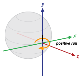
الشكل 3. الاتجاه بالنسبة إلى جهاز
يختلف هذا التعريف عن تعريفات الانحراف والميلان والتدحرج المستخدَمة في مجال الطيران، حيث يمتد المحور X على طول الجانب الطويل من الطائرة (من الذيل إلى المقدمة).
يُبلغ مستشعر الاتجاه أيضًا عن مدى دقة القراءات المتوقّعة من خلال sensors_event_t.orientation.status. راجِع ثوابت
SensorManager في
SENSOR_STATUS_* للحصول على مزيد من المعلومات حول القيم المحتملة لهذا الحقل.
أدوات الاستشعار غير المعايرة
تقدّم المستشعرات غير المعايرة نتائج أولية أكثر وقد تتضمّن بعض التحيزات، ولكنها تتضمّن أيضًا عددًا أقل من "القفزات" الناتجة عن التصحيحات التي يتم تطبيقها من خلال المعايرة. قد تفضّل بعض التطبيقات هذه النتائج غير المعايرة لأنّها أكثر سلاسة وموثوقية. على سبيل المثال، إذا كان أحد التطبيقات يحاول إجراء دمج بيانات أجهزة الاستشعار بنفسه، قد يؤدي إدخال عمليات المعايرة إلى تشويه النتائج.
مقياس التسارع غير معاير
جهاز الاستشعار المادي الأساسي: مقياس التسارع
Reporting-mode: Continuous
getDefaultSensor(SENSOR_TYPE_ACCELEROMETER_UNCALIBRATED)
تعرض هذه السمة جهاز استشعار غير مفعّل
يرصد مقياس التسارع غير المعاير تسارع الجهاز على طول محاور مقياس التسارع الثلاثة بدون أي تصحيح للانحياز (يتم تطبيق انحياز المصنع وتعويض درجة الحرارة على القياسات غير المعايرة)، بالإضافة إلى تقدير الانحياز.
تكون جميع القيم بوحدات النظام الدولي (م/ث^2) ويتم تسجيلها في حقول
sensors_event_t.uncalibrated_accelerometer:
-
x_uncalib: التسارع (بدون تعويض الانحياز) على طول المحور X -
y_uncalib: التسارع (بدون تعويض الانحياز) على طول المحور Y -
z_uncalib: التسارع (بدون تعويض الانحياز) على طول المحور Z x_bias: الانحياز المقدَّر على طول المحور X-
y_bias: الانحياز المقدَّر على طول المحور Y -
z_bias: الانحياز المقدَّر على طول المحور Z
الجيروسكوب غير معاير
مستشعر مادي أساسي: جيروسكوب
Reporting-mode: Continuous
getDefaultSensor(SENSOR_TYPE_GYROSCOPE_UNCALIBRATED)
تعرض هذه السمة جهاز استشعار غير مفعّل
يعرض الجيروسكوب غير المعاير معدّل الدوران حول محاور أداة الاستشعار
بدون تطبيق تعويض الانحراف عليها، بالإضافة إلى تقدير الانحراف. جميع القيم بوحدة راديان/ثانية ويتم عرضها في حقول sensors_event_t.uncalibrated_gyro:
-
x_uncalib: السرعة الزاوية (بدون تعويض الانحراف) حول المحور X -
y_uncalib: السرعة الزاوية (بدون تعويض الانحراف) حول المحور Y -
z_uncalib: السرعة الزاوية (بدون تعويض الانحراف) حول المحور Z -
x_bias: الانحراف المقدَّر حول المحور X y_bias: الانحراف المقدَّر حول المحور Yz_bias: الانحراف المقدَّر حول المحور Z
من الناحية النظرية، فإنّ القياس غير المعاير هو مجموع القياس المعاير وتقدير الانحياز: _uncalibrated = _calibrated + _bias.
من المتوقّع أن تتغيّر قيم x_bias وy_bias وz_bias بشكل كبير فور تغيُّر تقدير الانحياز، ومن المفترض أن تظل ثابتة في بقية الوقت.
راجِع تعريف مستشعر الجيروسكوب للحصول على تفاصيل حول نظام الإحداثيات المستخدَم.
يجب تطبيق المعايرة في المصنع وتعويض درجة الحرارة على القياسات. يجب أيضًا تنفيذ تقدير الانحراف في الجيروسكوب حتى يمكن عرض تقديرات معقولة في x_bias وy_bias وz_bias. إذا لم يكن التنفيذ قادرًا على تقدير الانحراف، يجب عدم تنفيذ هذا المستشعر.
وفي حال توفّر هذا المستشعر، يجب توفّر مستشعر الجيروسكوب المقابل أيضًا، ويجب أن يتشارك المستشعران القيمتَين sensor_t.name وsensor_t.vendor نفسيهما.
المجال المغناطيسي غير المعاير
جهاز الاستشعار المادي الأساسي: مقياس المغناطيسية
Reporting-mode: Continuous
getDefaultSensor(SENSOR_TYPE_MAGNETIC_FIELD_UNCALIBRATED)
تعرض هذه السمة جهاز استشعار غير مفعّل
يرصد مستشعر المجال المغناطيسي غير المعاير المجال المغناطيسي المحيط
بالإضافة إلى تقدير لمعايرة الحديد الصلب. جميع القيم بوحدة ميكرو تسلا
(uT) ويتم عرضها في حقول
sensors_event_t.uncalibrated_magnetic:
-
x_uncalib: المجال المغناطيسي (بدون تعويض الحديد الصلب) على طول المحور X -
y_uncalib: المجال المغناطيسي (بدون تعويض الحديد الصلب) على طول المحور Y z_uncalib: المجال المغناطيسي (بدون تعويض الحديد الصلب) على طول المحور Z-
x_bias: الانحياز المقدَّر للحديد الصلب على طول المحور X -
y_bias: الانحراف المقدَّر للحديد الصلب على طول المحور Y -
z_bias: الانحياز المقدَّر للحديد الصلب على طول المحور Z
من الناحية النظرية، فإنّ القياس غير المعاير هو مجموع القياس المعاير وتقدير الانحياز: _uncalibrated = _calibrated + _bias.
يسمح مقياس المغناطيسية غير المعاير للخوارزميات ذات المستوى الأعلى بالتعامل مع التقدير السيئ للحديد الصلب. من المتوقّع أن تتغيّر قيم x_bias وy_bias وz_bias بشكل كبير فور تغيُّر تقدير الحديد الصلب، ومن المفترض أن تظل ثابتة في بقية الوقت.
يجب تطبيق معايرة الحديد اللين وتعويض درجة الحرارة على القياسات. يجب أيضًا تنفيذ تقدير التشويش المغناطيسي الثابت حتى يمكن عرض تقديرات معقولة في x_bias وy_bias وz_bias. إذا لم يكن التنفيذ قادرًا على تقدير الانحياز، يجب عدم تنفيذ هذا المستشعر.
في حال توفّر هذا المستشعر، يجب توفّر مستشعر المجال المغناطيسي المقابل، ويجب أن يتشارك المستشعران القيمتَين sensor_t.name وsensor_t.vendor.
زاوية المفصّلة
Reporting-mode: On-change
getDefaultSensor(SENSOR_TYPE_HINGE_ANGLE)
تعرض مستشعر تنبيه
يقيس مستشعر زاوية المفصلة الزاوية بالدرجات بين جزأين متكاملَين من الجهاز. من المتوقّع أن يؤدي تحرّك المفصلة الذي يتم قياسه بواسطة هذا النوع من المستشعرات إلى تغيير الطرق التي يمكن للمستخدم التفاعل بها مع الجهاز، مثلاً من خلال فتح شاشة أو إظهارها.
أجهزة استشعار مركّبة للتفاعل
تُستخدم بعض أدوات الاستشعار في الغالب لرصد التفاعلات مع المستخدم. لا نحدّد طريقة تنفيذ هذه المستشعرات، ولكن يجب أن تكون منخفضة استهلاك الطاقة، ويتحمّل مصنّع الجهاز مسؤولية التحقّق من جودتها من حيث تجربة المستخدم.
إيماءة التنشيط
أجهزة الاستشعار المادية الأساسية: غير محدّد (أي جهاز استشعار منخفض الطاقة)
Reporting-mode: One-shot
طاقة منخفضة
يجب تنفيذ إصدار التنشيط فقط من جهاز الاستشعار هذا.
getDefaultSensor(SENSOR_TYPE_WAKE_GESTURE)
تعرض أداة استشعار لتشغيل الكاميرا
يتيح مستشعر إيماءة التنشيط تنشيط الجهاز استنادًا إلى حركة خاصة بالجهاز. عندما يتم تنشيط هذا المستشعر، يتصرف الجهاز كما لو تم الضغط على زر التشغيل، ما يؤدي إلى تشغيل الشاشة. يمكن للمستخدم إيقاف هذا السلوك (تفعيل الشاشة عند تشغيل هذا المستشعر) في إعدادات الجهاز. لا تؤثر التغييرات في الإعدادات في سلوك المستشعر، بل في ما إذا كان الإطار يفعّل الشاشة عند تشغيله. لم يتم تحديد الإيماءة الفعلية التي سيتم رصدها، ويمكن أن تختارها الشركة المصنّعة للجهاز.
يجب أن يكون هذا المستشعر منخفض الطاقة، لأنّه من المحتمل أن يتم تفعيله على مدار الساعة طوال أيام الأسبوع.
يُبلغ كل حدث من أحداث المستشعر عن 1 في sensors_event_t.data[0].
إيماءة الالتقاط
أجهزة الاستشعار المادية الأساسية: غير محدّد (أي جهاز استشعار منخفض الطاقة)
Reporting-mode: One-shot
طاقة منخفضة
يجب تنفيذ إصدار التنشيط فقط من جهاز الاستشعار هذا.
getDefaultSensor(SENSOR_TYPE_PICK_UP_GESTURE)
تعرض أداة استشعار لتشغيل الكاميرا
يتم تفعيل مستشعر إيماءة الالتقاط عند التقاط الجهاز بغض النظر عن مكانه السابق (المكتب أو الجيب أو الحقيبة).
يُبلغ كل حدث من أحداث المستشعر عن 1 في sensors_event_t.data[0].
إيماءة النظرة السريعة
أجهزة الاستشعار المادية الأساسية: غير محدّد (أي جهاز استشعار منخفض الطاقة)
Reporting-mode: One-shot
طاقة منخفضة
يجب تنفيذ إصدار التنشيط فقط من جهاز الاستشعار هذا.
getDefaultSensor(SENSOR_TYPE_GLANCE_GESTURE)
تعرض أداة استشعار لتشغيل الكاميرا
يتيح مستشعر الإيماءات السريعة تشغيل الشاشة لفترة وجيزة لتمكين المستخدم من إلقاء نظرة سريعة على المحتوى المعروض على الشاشة استنادًا إلى حركة معيّنة. عندما يتم تفعيل هذا المستشعر، سيضيء الجهاز الشاشة لفترة وجيزة ليتمكّن المستخدم من إلقاء نظرة سريعة على الإشعارات أو المحتوى الآخر بينما يظل الجهاز مقفلاً وفي حالة غير تفاعلية (وضع الغفوة)، ثم ستنطفئ الشاشة مرة أخرى. يمكن للمستخدم إيقاف هذا السلوك (تفعيل الشاشة لفترة وجيزة عند تشغيل أداة الاستشعار) من خلال إعدادات الجهاز. لا تؤثر التغييرات في الإعدادات في سلوك المستشعر، بل تحدّد فقط ما إذا كان سيتم تشغيل الشاشة لفترة وجيزة عندما يتم تفعيل الإطار. لا يتم تحديد الإيماءة الفعلية التي سيتم رصدها، ويمكن أن تختارها جهة تصنيع الجهاز.
يجب أن يكون هذا المستشعر منخفض الطاقة، لأنّه من المحتمل أن يتم تفعيله على مدار الساعة طوال أيام الأسبوع.
يُبلغ كل حدث من أحداث المستشعر عن 1 في sensors_event_t.data[0].
مستشعرات وحدة القياس بالقصور الذاتي (IMU) ذات المحاور المحدودة
تتوفّر مستشعرات وحدة القياس بالقصور الذاتي (IMU) ذات المحاور المحدودة بدءًا من Android 13، وهي مستشعرات تتيح حالات استخدام لا تتوفّر فيها جميع المحاور الثلاثة (س، ص، ع). تفترض أنواع IMU العادية في Android (مثل
SENSOR_TYPE_ACCELEROMETER
و
SENSOR_TYPE_GYROSCOPE)
أنّه يتم توفير جميع المحاور الثلاثة. ومع ذلك، لا تتوافق بعض أشكال الأجهزة وأنواعها مع مقاييس التسارع الثلاثية المحاور ومقاييس الدوران الثلاثية المحاور.
محاور مقياس التسارع المحدودة
أجهزة الاستشعار المادية الأساسية: مقياس التسارع
Reporting-mode: Continuous
getDefaultSensor(SENSOR_TYPE_ACCELEROMETER_LIMITED_AXES)
تعرض هذه السمة جهاز استشعار غير مفعّل
جهاز استشعار التسارع المحدود المحاور يعادل
TYPE_ACCELEROMETER ولكنّه يتيح حالات لا يتوفّر فيها محور واحد أو محوران.
تمثّل آخر ثلاث قيم لأحداث المستشعر التي أبلغ عنها المستشعر ما إذا كانت قيمة التسارع لمحاور x وy وz متوافقة. تشير القيمة 1.0 إلى أنّ المحور متوافق، وتشير القيمة 0 إلى أنّه غير متوافق. تحدّد الشركات المصنّعة للأجهزة المحاور المتوافقة في وقت الإنشاء، ولا تتغيّر القيم أثناء وقت التشغيل.
على الشركات المصنّعة للأجهزة ضبط قيم التسارع للمحاور غير المستخدَمة على 0 بدلاً من تركها بدون تحديد.
محاور الجيروسكوب المحدودة
أجهزة الاستشعار المادية الأساسية: الجيروسكوب
Reporting-mode: Continuous
getDefaultSensor(SENSOR_TYPE_GYROSCOPE_LIMITED_AXES)
تعرض هذه السمة جهاز استشعار غير مفعّل
مستشعر الجيروسكوب ذو المحاور المحدودة يعادل TYPE_GYROSCOPE
ولكنّه يتيح حالات لا يتوفّر فيها محور واحد أو محوران.
تمثّل آخر ثلاث قيم لأحداث المستشعر التي أبلغ عنها المستشعر ما إذا كانت قيمة السرعة الزاوية للمحاور x وy وz متوافقة. تشير القيمة 1.0 إلى أنّ المحور متوافق، وتشير القيمة 0 إلى أنّه غير متوافق. تحدّد الشركات المصنّعة للأجهزة المحاور المتوافقة في وقت الإنشاء، ولا تتغيّر القيم أثناء وقت التشغيل.
على الشركات المصنّعة للأجهزة ضبط قيم السرعة الزاوية للمحاور غير المستخدَمة على 0.
محاور مقياس التسارع المحدودة غير معايرة
أجهزة الاستشعار المادية الأساسية: مقياس التسارع
Reporting-mode: Continuous
getDefaultSensor(SENSOR_TYPE_ACCELEROMETER_LIMITED_AXES_UNCALIBRATED)
تعرض هذه السمة جهاز استشعار غير مفعّل
جهاز استشعار التسارع ذو المحاور المحدودة غير المعايرة يعادل
TYPE_ACCELEROMETER_UNCALIBRATED ولكنّه يتيح حالات لا يتوفّر فيها محور واحد أو محوران.
تمثّل قيم أحداث الاستشعار الثلاث الأخيرة التي أبلغ عنها المستشعر ما إذا كانت قيم التسارع والانحياز للمحاور x وy وz متاحة. تشير القيمة 1.0 إلى أنّ المحور متوافق، وتشير القيمة 0 إلى أنّه غير متوافق. تحدّد الشركات المصنّعة للأجهزة المحاور المتوافقة في وقت الإنشاء، ولا تتغيّر القيم أثناء وقت التشغيل.
على الشركات المصنّعة للأجهزة ضبط قيم التسارع والانحياز للمحاور غير المستخدَمة على 0.
محاور الجيروسكوب المحدودة غير المعايرة
أجهزة الاستشعار المادية الأساسية: الجيروسكوب
Reporting-mode: Continuous
getDefaultSensor(SENSOR_TYPE_GYROSCOPE_LIMITED_AXES_UNCALIBRATED)
تعرض هذه السمة جهاز استشعار غير مفعّل
مستشعر جيروسكوب محدود المحاور غير معاير يعادل TYPE_GYROSCOPE_UNCALIBRATED، ولكنّه يتيح حالات لا تتوفّر فيها إمكانية استخدام محور واحد أو محورَين.
تمثّل آخر ثلاث قيم لأحداث المستشعر التي أبلغ عنها المستشعر ما إذا كانت قيم السرعة الزاوية والانحراف لمحاور x وy وz متوافقة. تشير القيمة 1.0 إلى أنّ المحور متوافق، وتشير القيمة 0 إلى أنّه غير متوافق. تحدّد الشركات المصنّعة للأجهزة المحاور المتوافقة في وقت الإنشاء، ولا تتغيّر القيم أثناء وقت التشغيل.
على الشركات المصنّعة للأجهزة ضبط قيمتَي السرعة الزاوية والانحراف للمحاور غير المستخدَمة على 0.
وحدة قياس القصور الذاتي (IMU) ذات المحاور المحدودة المركّبة
أدوات الاستشعار الفيزيائية الأساسية: أي مجموعة من مقياس التسارع الثلاثي المحاور والجيروسكوب الثلاثي المحاور ومقياس التسارع الثلاثي المحاور غير المعاير والجيروسكوب الثلاثي المحاور غير المعاير.
Reporting-mode: Continuous
مستشعر وحدة القياس بالقصور الذاتي (IMU) المحدود المحاور المركّب هو مستشعر وحدة قياس بالقصور الذاتي (IMU) محدود المحاور، ولكن بدلاً من أن يكون متوافقًا مع طبقة تجريد الأجهزة (HAL)، يحوّل بيانات المستشعر الثلاثي المحاور إلى متغيرات محدودة المحاور مكافئة. لا يتم تفعيل أجهزة الاستشعار المركّبة هذه إلا للأجهزة المخصّصة للسيارات.
يوضّح الجدول التالي مثالاً على عملية تحويل من مقياس تسارع عادي ثلاثي المحاور إلى مقياس تسارع مركب محدود المحاور.
| قيم SensorEvent الخاصة بـ SENSOR_TYPE_ACCELEROMETER | مثال على SensorEvent من النوع SENSOR_TYPE_ACCELEROMETER | Composite SENSOR_TYPE_ACCELEROMETER_LIMITED_AXES SensorEvent |
|---|---|---|
| values[0] | -0.065 |
-0.065 |
| values[1] | 0.078 |
0.078 |
| values[2] | 9.808 |
9.808 |
| values[3] | لا ينطبق |
1 |
| values[4] | لا ينطبق |
1 |
| values[5] | لا ينطبق |
1 |
مستشعرات السيارات
أجهزة الاستشعار التي تتيح حالات استخدام السيارات
العنوان
أدوات الاستشعار المادية الأساسية: أي مجموعة من نظام تحديد المواقع العالمي (GPS) ومقياس المغناطيسية ومقياس التسارع والجيروسكوب
Reporting-mode: Continuous
getDefaultSensor(SENSOR_TYPE_HEADING)
تعرض هذه السمة جهاز استشعار غير مفعّل
يتوفّر هذا المستشعر في الإصدار 13 من نظام التشغيل Android، وهو يقيس الاتجاه الذي يشير إليه الجهاز بالنسبة إلى الشمال الحقيقي بالدرجات. يتضمّن مستشعر الاتجاه قيمتَين SensorEvent.
أحدهما لعنوان الجهاز الذي تم قياسه والآخر لدقة قيمة العنوان المقدَّمة.
يجب أن تتراوح قيم العنوان التي يرصدها هذا المستشعر بين 0.0 (ضمناً) و360.0 (باستثناء)، مع الإشارة إلى الشمال بـ 0 والشرق بـ 90 والجنوب بـ 180 والغرب بـ 270.
يتم تحديد دقة أداة الاستشعار هذه عند مستوى ثقة يبلغ %68. في الحالة التي يكون فيها التوزيع الأساسي عاديًا وفقًا لمنحنى غاوس، تكون الدقة هي انحراف معياري واحد. على سبيل المثال، إذا كان مستشعر الاتجاه يعرض قيمة اتجاه تبلغ 60 درجة وقيمة دقة تبلغ 10 درجات، يكون هناك احتمال بنسبة %68 أن يكون الاتجاه الحقيقي بين 50 درجة و70 درجة.