為配合主幹穩定開發模型,並確保生態系統的平台穩定性,我們將自 2026 年起,在第 2 季和第 4 季將原始碼發布至 AOSP。如要建構及貢獻 AOSP,請使用 android-latest-release。android-latest-release 資訊清單分支版本一律會參照推送至 Android 開放原始碼計畫的最新版本。詳情請參閱「Android 開放原始碼計畫變更」。
 Google uses AI technology to translate content into your preferred language. AI translations can contain errors.
音訊回送連接器
透過集合功能整理內容
你可以依據偏好儲存及分類內容。
下圖和相片顯示耳機連接器的音訊迴路 連接器。Chrome 硬體團隊設計這個電路和插頭,用於功能測試;不過,它還有許多其他用途。Android 音訊團隊會透過這項功能,透過輸出端傳送已編碼的訊號,然後在輸入端尋找相符的訊號,以便測量往返音訊延遲時間。這兩者之間的時間就是輸入加上輸出延遲的總和。這種方法會用於 OboeTester 和 CTS Verifier。
您可以向 PassMark Software 索取以下電路為基礎的迴送式 Dongle。這並非推薦或認可。Google 與 PassMark 之間沒有任何商業關係。
電路
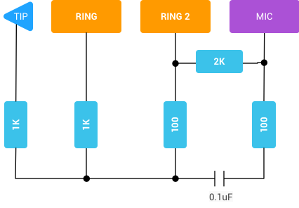
圖 1.電路圖
為確保輸出訊號不會造成麥克風輸入過載,我們將其降低約 20dB。電阻負載會告知麥克風極性開關,音訊迴路 dongle 是 US/CTIA 針腳排列的 Tip Ring Ring Shield (TRRS) 插頭。
已組裝

圖 2. 已組裝
這個頁面中的內容和程式碼範例均受《內容授權》中的授權所規範。Java 與 OpenJDK 是 Oracle 和/或其關係企業的商標或註冊商標。
上次更新時間:2025-02-27 (世界標準時間)。
[[["容易理解","easyToUnderstand","thumb-up"],["確實解決了我的問題","solvedMyProblem","thumb-up"],["其他","otherUp","thumb-up"]],[["缺少我需要的資訊","missingTheInformationINeed","thumb-down"],["過於複雜/步驟過多","tooComplicatedTooManySteps","thumb-down"],["過時","outOfDate","thumb-down"],["翻譯問題","translationIssue","thumb-down"],["示例/程式碼問題","samplesCodeIssue","thumb-down"],["其他","otherDown","thumb-down"]],["上次更新時間:2025-02-27 (世界標準時間)。"],[],[]]
