自 2026 年起,为了与我们的主干稳定开发模型保持一致,并确保生态系统的平台稳定性,我们将在第 2 季度和第 4 季度将源代码发布到 AOSP。对于构建 AOSP 和向 AOSP 贡献代码,我们建议使用 android-latest-release 而不是 aosp-main。android-latest-release 清单分支将始终引用推送到 AOSP 的最新版本。如需了解详情,请参阅 AOSP 变更。
音频环回适配器
使用集合让一切井井有条
根据您的偏好保存内容并对其进行分类。
下面的图表和照片展示的是耳机连接器的音频环回dongle。Chrome 硬件团队设计了此电路和插头以进行功能测试,不过它还有许多其他用途。Android 音频团队使用它测量往返音频延迟时间,具体做法为:通过输出端发送已编码信号,然后在输入端查找匹配的信号。两者的间隔时间就是输入端加输出端的整体延迟时间。OboeTester 和 CTS 验证程序中都运用了这一技术。
PassMark Software 出售一款基于以下电路的环回适配器。这并非我们对该产品的推荐或背书。Google 与 PassMark 没有业务往来。
电路
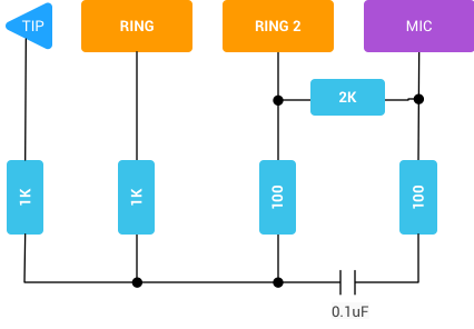
图 1. 电路图
为了确保输出信号不会超出麦克风输入负荷,我们使其音量降低了约 20 分贝。麦克风极性开关可从电阻器负载得知,音频环回适配器是一种美标/CTIA 4 段式 TRRS 插头。
组装完成图
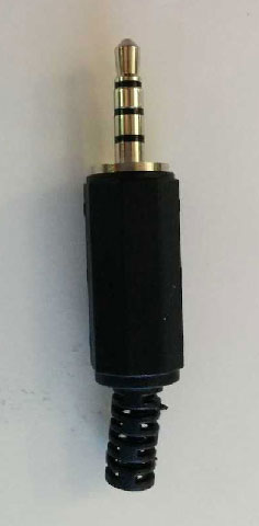
图 2. 组装完成图
本页面上的内容和代码示例受内容许可部分所述许可的限制。Java 和 OpenJDK 是 Oracle 和/或其关联公司的注册商标。
最后更新时间 (UTC):2025-03-04。
[[["易于理解","easyToUnderstand","thumb-up"],["解决了我的问题","solvedMyProblem","thumb-up"],["其他","otherUp","thumb-up"]],[["没有我需要的信息","missingTheInformationINeed","thumb-down"],["太复杂/步骤太多","tooComplicatedTooManySteps","thumb-down"],["内容需要更新","outOfDate","thumb-down"],["翻译问题","translationIssue","thumb-down"],["示例/代码问题","samplesCodeIssue","thumb-down"],["其他","otherDown","thumb-down"]],["最后更新时间 (UTC):2025-03-04。"],[],[]]
