
Android 16 introduced the Ranging module. This protocol and payload specification defines the message sequence and the payload of out-of-band (OOB) communication used to exchange ranging configurations, and to start and stop ranging, between the initiator and the responder device that engage in ranging. Android 17 introduces version 3 of this specification.
This page describes how non-Android device providers can implement this specification so that their devices are compatible with Android devices.
An implementation of this specification in Google's Packet Description Language (PDL) is available on GitHub. From this implementation, the PDL compiler can generate serialization and deserialization code for the messages defined in this specification. This specification supports a variety of target languages including C++, Rust, and Java.
What's new in version 3
Version 3 of the OOB specification introduces the following changes:
- Motion Notification: A message that the advertiser device uses to notify the initiating device of a motion change.
- Ranging Configuration: Includes a new
Motion supportfield to tell the initiator to notify the responder of any changes in the peripheral movement from the responder. - Add new Wi-Fi PD technogoloy support in Ranging Capability and Ranging Configuration.
- Deprecate
Supported BandwidthandSupported number of Receive chainsfields inWi-Fi NAN RTT Ranging Capability.
Endianness
Unless otherwise specified, all multi-byte numeric fields in the messages are in little-endian order.
Messages and message sequence
This section describes the messages and the sequence of the message exchange.
The following table shows all the messages that are present in the OOB exchange:
| Message | Message ID |
|---|---|
Ranging Capability Request |
0x0 |
Ranging Capability Response |
0x1 |
Ranging Configuration |
0x2 |
Ranging Configuration Response (optional) |
0x3 |
Stop Ranging |
0x6 |
Stop Ranging Response (optional) |
0x7 |
Motion Notification |
0x8 |
The message exchange starts with the initiator device sending Ranging
Capability Request to the responder device. The responder device replies by
sending Ranging Capability Response, as shown in Figure 1:
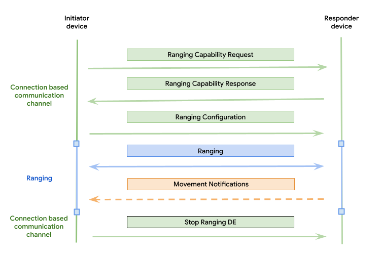
Figure 1. OOB message exchange using a connection-based communication channel.
The responder device starts ranging immediately after receiving the Ranging
Configuration message. The responder device stops ranging after it receives or
detects the Stop Ranging message.
The responder device populates the capabilities
only of the ranging technologies requested in the Ranging Capability Request
message.
The initiator device expects to receive only one response to any request message
it sends. The responder device must not make any such assumptions so that it can
respond to any request in any order. This verifies that the responder device can
respond to multiple consecutive Ranging Capability Request messages, or any
other out-of-order messages, from the initiator device.
Technology transitioning
The OOB version lets the devices dynamically transition between different ranging technologies during a session. To facilitate this, the initiator can:
- Send multiple
Ranging Configurationmessages to start new technologies. - Send multiple
Stop Rangingmessages to stop active technologies.
The order of these messages varies depending on the transitioning scheme supported by the responder:
- Break-before-make: The initiator can transition to a new technology only
by stopping the first with a
Stop Rangingmessage before starting the second with aRanging Configurationmessage. - Make-before-break: The initiator can start a new technology using a
Ranging Configurationmessage before stopping existing technologies with aStop Rangingmessage.
The responder must implement support for one of these transitioning schemes in
accordance with the value of the supported technology transitioning field
in its Ranging Capability Response.
Ranging technology IDs
The IDs of the ranging technologies are listed in the following table:
| Ranging technology | ID |
|---|---|
| UWB | 0x0 |
| CS | 0x1 |
| Wi-Fi NAN RTT | 0x2 |
| RSSI | 0x3 |
| Wi-Fi PD | 0x4 |
| RFU | 0x5 - 0xFF |
These IDs are used in the tables on this page where the ranging technology ID is required. For fields containing ranging technology bitfield, a bit corresponding to the index of the ID of the technology is set when that technology is included in the bitfield.
For example, RSSI has an ID value 3, but if RSSI is included in the ranging technology bitfield, then the bit with position of the ID (3) must be switched on (first bit being at position 0), which makes the resulting value of the bitfield 0x8. If both UWB and RSSI are included, then the value of the bitfield is 0x0A (both bits 0 and 3 switched on).
Message format
Each message consists of a header and a payload.
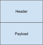
Figure 3. Message format.
Header
Size: 2 bytes
Description: Common across all messages, the header is the first part that goes into a message. The header contains a version and the ID of the message type. The version field specifies the version of this specification that the contents of the message conform to. For more information on how versioning is used between devices on different versions, see Versioning. The header remains backward compatible across different versions, which means the use case can always parse it to determine the version and the ID of the message.
The header is summarized in the following table:
| Octet | Data type | Description | Value |
|---|---|---|---|
| 0 | uint8 | Version |
|
| 1 | uint8 | Message ID |
|
Payload
Size: Varies (depends on the type of the message)
Description: Payload is the last part of the message, after the header. The payload depends on the type of the message. The format for the payload of each individual message type is defined in the following sections.
Ranging Capability Request message payload
Size (header size not included): 2 bytes
Description: Sent by the initiator device to initiate the message exchange.
The Ranging Capability Request message payload is summarized in the following
table:
| Octet | Data type | Description | Value |
|---|---|---|---|
| 0 | uint8*2 | Requested ranging technologies bitfield |
|
Ranging Capability Response message payload
Size (header size not included): Varies (common part 2 bytes plus the size of each included ranging technology bytes)
Description: Sent by the responder as a response to a Ranging Capability
Request message. This message payload consists of the common part, and ranging
technology-specific parts (BLE CS, Wi-Fi NAN RTT, BLE RSSI), as shown in the
following tables. Each ranging technology-specific part must be added only if
that ranging technology is supported by the responder device and is requested in
the Ranging Capability Request message.
The common Ranging Capability Response message payload is summarized in the
following table:
| Octet | Data type | Description | Value |
|---|---|---|---|
| 0 | uint8*2 | Supported ranging technologies bitfield. Indicates the set of capabilities of ranging technologies that follow in the rest of the payload. |
|
| 2 | byte array | Ranging technology capability bytes. | Repeated blocks of structs defined per technology. |
| Varies | uint8 | Indicates support for technology transitioning. |
|
| Varies | uint16 | Indicates the type of the responder device. |
|
The UWB Ranging Capability Response message payload is summarized in the
following table:
| Octet | Data type | Description | Value |
|---|---|---|---|
| 0 | uint8 | Ranging technology ID | 0x0 - UWB |
| 1 | uint8 | Size | Size of UWB capabilities bytes (including Technology ID and Size fields) in bytes. |
| 2 | uint8*2 | UWB address | 2 byte device UWB address. |
| 4 | uint8*4 | Supported channels bitfield | Bitfield of supported channels. Bit set to 0 indicates not supported, 1 indicates supported. Bit 0 corresponds to channel 0.LSB == channel 0MSB == channel 31 |
| 8 | uint8*4 | Supported preamble index bitfield | Bitfield of supported preamble indexes. Bit set to 0 indicates not supported, 1 indicates supported. Bit 0 corresponds to preamble index 1.LSB == preamble index 1MSB == preamble index 32 |
| 12 | uint8*4 | Supported config IDs bitfield | Bitfield of supported UWB config IDs. Bit set to 0 indicates not supported, 1 indicates supported.LSB == config Id 0MSB == config Id 31 |
| 16 | uint8*2 | Supported minimum ranging interval | Indicates the fastest supported ranging interval in milliseconds. Allowed values (in ms):
|
| 18 | uint8 | Supported minimum slot duration | Indicates the smallest supported slot duration in milliseconds. For example, if the device returns 1 ms then it's assumed it also supports 2 ms or higher slot durations. Allowed values (in ms):
|
| 19 | uint8 | Supported UWB device role bitfield | Bitfield of the supported UWB roles. For example, if both supported the final field value is 0x3.
|
The BLE CS Ranging Capability Response message payload is summarized in the
following table:
| Octet | Data type | Description | Value |
|---|---|---|---|
| 0 | uint8 | Ranging technology ID | 0x1 - BLE CS |
| 1 | uint8 | Size | Size of BLE CS capabilities bytes (including Technology ID and Size fields) in bytes. |
| 2 | uint8 | Supported security type bitfield | Bitfield of supported security types for BLE CS.
|
| 3 | uint8*6 | Device address | The address of the device used for BLE CS; in big-endian order. |
The Wi-Fi NAN RTT Ranging Capability Response message payload is summarized
in the following table:
| Octet | Data type | Description | Value |
|---|---|---|---|
| 0 | uint8 | Ranging technology ID | 0x2 - Wi-Fi NAN RTT |
| 1 | uint8 | Size | Size of Wi-Fi NAN RTT capabilities bytes (including Technology ID and Size fields) in bytes. |
| 2 | uint8 | Supported features bitfield | Bitfield of supported features.
|
| 3 | uint8 | Supports periodic ranging |
|
| 4 | uint8 | Supported bandwidth | DEPRECATED: This information helps derive the
achievable ranging accuracy using Wi-Fi NAN and can help apps determine
whether to use UWB, BLE CS, BLE RSSI, or Wi-Fi NAN for ranging.
|
| 5 | uint8 | Supported number of receive chains | DEPRECATED: This information helps derive the achievable ranging accuracy using Wi-Fi NAN and can help apps determine whether to use UWB, BLE CS, BLE RSSI, or Wi-Fi NAN for ranging.
|
The BLE RSSI Ranging Capability Response message payload is summarized in the
following table:
| Octet | Data type | Description | Value |
|---|---|---|---|
| 0 | uint8 | Ranging technology ID | 0x3 - BLE RSSI |
| 1 | uint8 | Size | The size of BLE RSSI capabilities bytes (including Technology ID and Size fields) in bytes |
| 2 | uint8*6 | Device address | The address of the device used for BLE RSSI; in big-endian order |
The Wi-Fi PD Ranging Capability Response message payload is summarized in the
following table:
| Octet | Data type | Description | Value |
|---|---|---|---|
| 0 | uint8 | Ranging technology ID | 0x4 - Wi-Fi PD |
| 1 | uint8 | Size | The size of Wi-Fi PD capabilities bytes (including Technology ID and Size fields) in bytes |
| 2 | uint8 | Supported features | Bitmap
|
| 3 | uint8 | PASN mode | Bitmap
|
| 4 | uint8*6 | Device address | The address of the device used for Wi-Fi PD; in big-endian order. |
| 10 | uint8*2 | Min ranging interval 802.11mc | Minimum ranging interval supported in big-endian format for 11mc |
| 12 | uint8*2 | Min ranging interval 802.11az | Minimum ranging interval supported in big-endian format for 11az |
| 14 | uint8 | Max preamble type |
This assumes that all lower preamble types are supported. |
| 15 | uint8 | Max channel width |
This assumes that all lower channel widths are supported. |
| 16 | uint8*2 | Supported channel frequency |
|
Ranging Configuration message payload
Size (header size not included): Varies (common part 4 bytes plus the size of each included ranging technology bytes).
Description: This message is sent by the initiator and it contains the configurations that each ranging technology can start ranging with. The responder device must try to start ranging with each indicated ranging technology upon receiving this message. This message payload consists of the common part, and ranging technology-specific parts (UWB, BLE CS, Wi-Fi NAN RTT, BLE RSSI), as shown in the following tables.
The common Ranging Configuration message payload is summarized in the
following table:
| Octet | Data type | Description | Value |
|---|---|---|---|
| 0 | uint8*2 | Ranging technologies configuration set bitfield | Bitfield of ranging technologies that this message contains configuration data for and for which configuration parameters must be set.
|
| 2 | uint8*2 | Bitfield | RFU. Must be set to the same value as the Ranging technologies configuration set bitfield field. |
| 4 | byte array | Ranging technologies configurations bytes | Repeated blocks of structs defined per technology |
| Varies | uint8 | Motion support | Motion Notification requested
|
The UWB Ranging Configuration message payload is summarized in the following
table:
| Octet | Data type | Description | Value |
|---|---|---|---|
| 0 | uint8 | Ranging technology ID | 0x0 - UWB |
| 1 | uint8 | Size | Size of UWB configuration (including Technology ID and Size fields) in bytes |
| 2 | uint8*2 | UWB address | 2 byte device UWB address |
| 4 | uint8*4 | Session ID | Generated session ID. Session ID is a unique identifier for the ranging session between the phone and the peripheral. |
| 8 | uint8 | Selected config ID | Selected config ID number in integer. The config ID specifies the timing parameters and the type of security that must be used for the UWB ranging session. |
| 9 | uint8 | Selected channel | Selected channel for the UWB ranging session |
| 10 | uint8 | Selected preamble index | Selected preamble index for the UWB ranging session |
| 11 | uint8*2 | Selected ranging interval | Selected ranging interval rate in milliseconds. Allowed values (in ms):
|
| 13 | uint8 | Selected slot duration | Selected slot duration in milliseconds. Allowed values (in ms):
|
| 14 | uint8 | Session key length | Length of the session key in bytes |
| 15 | byte array | Session key | Session key. If S-STS is used then the first two bytes are VENDOR ID and the following six bytes are STATIC STS IV. If P-STS is used, this is either a 16 byte or 32 byte session key. The type of security used is determined by the config ID. |
| varies | uint8*2 | Country code | ISO 3166-1 alpha-2 country code, represented by two ASCII characters |
| varies | uint8 | Selected device role |
|
| varies | uint8 | Selected device mode |
|
The BLE CS Ranging Configuration message payload is summarized in the
following table:
| Octet | Data type | Description | Value |
|---|---|---|---|
| 0 | uint8 | Ranging technology ID | 0x1 - BLE CS |
| 1 | uint8 | Size | Size of BLE CS configuration (including Technology ID and Size fields) in bytes |
| 2 | uint8 | Selected security type | Selected security type. Allowed values:
|
| 3 | uint8*6 | Device address | The address of the device used for BLE CS; in big-endian order |
The Wi-Fi NAN RTT Ranging Configuration message payload is summarized in the
following table:
| Octet | Data type | Description | Value |
|---|---|---|---|
| 0 | uint8 | Ranging technology ID | 0x2 - Wi-Fi NAN RTT |
| 1 | uint8 | Size | Size of Wi-Fi NAN RTT configuration (including Technology ID and Size fields) in bytes |
| 2 | uint8 | Service name length | Length of the Service name field in bytes. Refer to Wi-Fi Aware Specification v4.0 section 1.3.3 Table 1. Definitions. |
| 3 | byte array | Service name | Service name. Refer to Wi-Fi Aware Specification v4.0 section 1.3.3 Table 1. Definitions. |
| varies | uint8 | Device role |
|
| varies | uint8 | Use periodic ranging |
|
The BLE RSSI Ranging Configuration message payload is summarized in the
following table:
| Octet | Data type | Description | Value |
|---|---|---|---|
| 0 | uint8 | Ranging technology ID | 0x3 - BLE RSSI |
| 1 | uint8 | Size | Size of BLE RSSI configuration (including Technology ID and Size fields) in bytes |
| 2 | uint8*6 | Device address | The address of the device used for BLE RSSI; in big-endian order |
The Wi-Fi PD Ranging Configuration message payload is summarized in the
following table:
| Octet | Data type | Description | Value |
|---|---|---|---|
| 0 | uint8 | Ranging technology ID | 0x4 - Wi-Fi PD |
| 1 | uint8 | Size | Size of Wi-Fi PD configuration (including Technology ID and Size fields) in bytes |
| 2 | uint8 | Feature |
|
| 3 | uint8*6 | MAC address | Initiator MAC address |
| 9 | uint8*2 | Ranging interval | Ranging interval in ms |
| 11 | uint8 | Selected preamble |
|
| 12 | uint8 | Selected channel width |
|
| 13 | uint8 | Selected channel |
|
| 14 | uint8 | Selected PASN mode |
|
| 15 | byte array | Device identity key | 16 byte fixed array Note: This field is valid only for authenticated PASN mode, must not be set for unauthenticated PASN mode |
| 31 | uint8 | Password length | Length of password. Note: This field is valid only for authenticated PASN mode, must not be set for unauthenticated PASN mode. |
| varies | byte array | Password | Password as byte array.
Note: This field is valid only for authenticated PASN mode, must not be set for unauthenticated PASN mode. |
Ranging Configuration Response message payload
Size (header size not included): 2 bytes
Description: This message is sent by the responder as a response to the
Ranging Configuration message. This message is optional; it's required only
when the used communication channel requires an explicit response for each
request.
The Ranging Configuration Response message payload is summarized in the
following table:
| Octet | Data type | Description | Value |
|---|---|---|---|
| 0 | uint8*2 | Ranging technologies configuration set successfully bitfield | Bitfield of ranging technologies that were set successfully. The bitfield sets the ranging technology bit to 1 if the technology was requested and set successfully, and 0 otherwise.
|
Stop Ranging message payload
Size (header size not included): 2 bytes
Description: This message is sent by the initiator device when it's time to stop ranging with the specified ranging technology.
The Stop Ranging message payload is summarized in the following table:
| Octet | Data type | Description | Value |
|---|---|---|---|
| 0 | uint8*2 | Ranging technologies to stop bitfield | Bitfield of ranging technologies that must stop ranging. Bit set to 1 indicates the ranging technology must stop ranging, and 0 indicates the ranging technology either wasn't ranging in the first place, or that it must continue ranging if it was already ranging. For some ranging technologies (like CS) this is a no-op because ranging is initiated and stopped only on the initiator side.
|
Stop Ranging Response message payload
Size (header size not included): 2 bytes
Description: This message is sent by the responder as a response to the
Stop Ranging message. This message is optional, it's required only when the
used communication channel requires an explicit response for each request.
The Stop Ranging Response message payload is summarized in the following
table:
| Octet | Data type | Description | Value |
|---|---|---|---|
| 0 | uint8*2 | Ranging technologies stopped successfully bitfield | Bitfield of ranging technologies that stopped ranging successfully. The bitfield sets the ranging technology bit to 1 if the technology was requested to be stopped and if it stopped successfully, and 0 otherwise.
|
Motion Notification message payload
Size (header size not included): 1 byte
Description: The responder device sends this message to inform the initiating device of any changes in its motion status.
| Octet | Data type | Description | Value |
|---|---|---|---|
| 0 | uint8 | Motion |
|
Versioning
The version of the specification is contained in the header of each message.
This section defines how communication is conducted when one of the devices
(either the initiator or the responder) is on an older version than the other
device. Ranging Capability Request is the first message sent by the initiator
device.
Initiator supports newer version, responder supports older version of specification
The initiator device sends the Ranging Capability Request message with the
newer version. The responder device supports only the older version, so it
responds with that, and then the responder's older version is used for the rest
of the message exchange. This means that the Ranging Capability Request
message has to be backward compatible.
Initiator supports older version, responder supports newer version of specification
The responder device sees that the initiator device isn't capable of using the newer version so it sends messages only using the older version requested initially by the initiator device.
To make sure messages are backward compatible, any new fields that are added to the next version of this specification must be appended to the end of the payload, and none of the existing fields can be modified. When parsing the configuration, if the indicated size is bigger than expected, additional fields must be ignored by any device that can understand only the older version of the specification.
Fragmentation
This specification is communication channel agnostic, so it doesn't define how to fragment the message payload in cases where a single message is too big to fit into a transfer packet of the communication channel used. The Ranging module expects to receive each message in its full form. The responsibility of the fragmentation lies on the implementor of the OOB communication channel.
Ranging-technology-specifics
This section contains details specific to ranging technology.
Ultra-wideband (UWB) specifics
This section describes ultra-wideband specific details.
Config IDs
OOB configuration data exchanged for UWB doesn't contain a full set of available configurable parameters that UWB requires to start a UWB ranging session. This is because some parameters are implicitly selected by the chosen config ID.
Each config ID is a set of predefined UWB configuration parameters that is
documented in
UwbRangingParams. The
responder device sends a list of all config IDs that it supports as part of the
capability response message, and the initiator selects one of the supported
config IDs that is used. This allows for a smaller set of config parameters to
be exchanged during OOB. It also limits the number of possible combinations of
parameters that can be used for ranging with UWB, which makes testing of only
allowed combinations of parameters possible.
Requesting capabilities after each UWB session
After stopping an existing UWB session and before starting a new UWB session, the initiator device must request the capabilities of the responder device and set the configuration parameters again, because the UWB address can rotate as soon as the current ranging session ends.
BLE channel sounding (CS) specifics
This section describes channel sounding specific details.
Required link encryption between devices
An existing bond between the initiator and the responder device is required for ranging using channel sounding to work. This specification doesn't provide a way for creating a bond between devices. You must establish this bond between the devices when using Ranging APIs.
Action required by the responder side for CS
In UWB, both devices are required to call the UWB start ranging and stop ranging
API explicitly. In contrast, for CS, only the initiator device is required to
start CS ranging by calling the BT stack. The rest of the
initialization on the responder side happens in band through BT. This means that
upon receiving the Ranging Configuration message or the Stop Ranging message
for CS, the responder side doesn't have to do anything if BT is enabled. The
responder device could use those messages as a trigger to update the UI or, for
example, blink the device LEDs.