
本節說明感應器軸、基本感應器和複合感應器 (活動、姿態、未校正和互動)。
感應器軸
許多感應器的感應器事件值會以特定影格表示,而該影格相對於裝置而言是靜態的。
行動裝置軸
Sensor API 只會相對於螢幕的自然方向 (裝置螢幕方向變更時,軸不會互換)。

圖 1. Sensor API 使用的座標系統 (相對於行動裝置)
Automotive 軸
在 Android Automotive 實作中,軸是相對於車身框架定義。車輛參考架構的原點是後軸的中心。車輛參考框架的方向如下:
- X 軸指向右側,位於水平平面上,垂直於車輛對稱平面。
- Y 軸指向前方,位於水平面上。
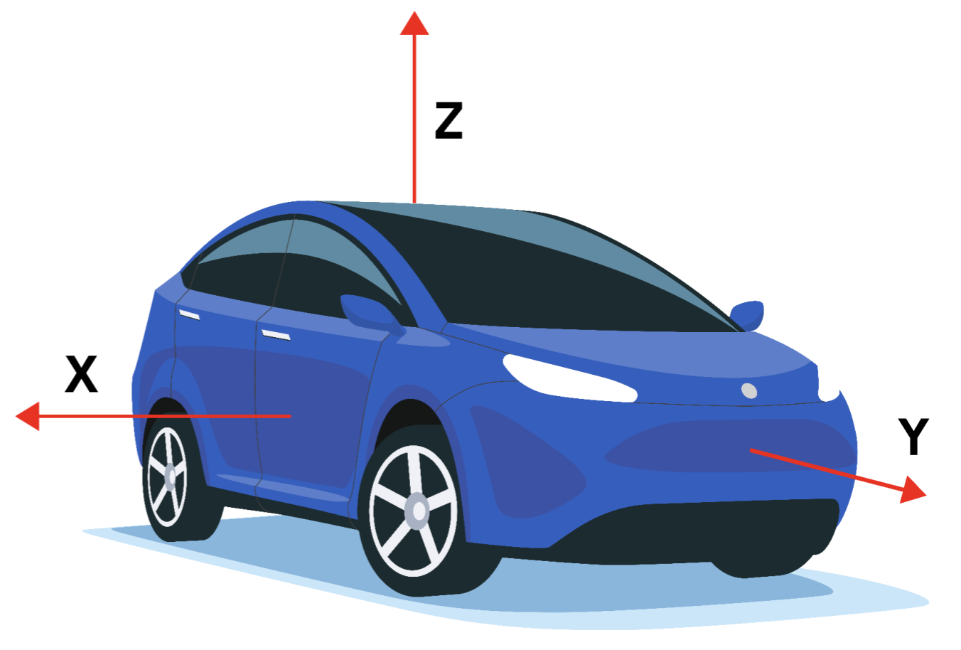
圖 2. Sensor API 使用的座標系統 (相對於汽車裝置)
車輛參考架構是右手座標系統。因此,Z 軸會向上指。
參考架構的 Z 軸會與重力方向一致,也就是說 X 軸和 Y 軸都是水平的。因此,Y 軸不一定會經過前軸。
基本感應器
基礎感應器類型是以其所代表的實體感應器命名。這些感應器會轉送單一實體感應器的資料 (與複合感應器不同,後者會從其他感應器產生資料)。基本感應器類型的範例包括:
SENSOR_TYPE_ACCELEROMETERSENSOR_TYPE_GYROSCOPESENSOR_TYPE_MAGNETOMETER
不過,基礎感應器與基礎感應器的基礎物理感應器不同,也不能混淆。基礎感應器的資料不是實體感應器的原始輸出,因為系統會套用修正 (例如偏差補償和溫度補償)。
舉例來說,在下列用途中,基礎感應器的特性可能與其基礎實體感應器的特性不同:
- 陀螺儀晶片的偏差範圍為 1 度/秒。
- 在工廠校正後,系統會套用溫度補償和偏差補償,Android 感應器的實際偏差會降低,可能會降到保證偏差低於 0.01 度/秒的程度。
- 在這種情況下,我們會說 Android 感應器的偏差值低於 0.01 度/秒,即使基礎感應器的資料表指出 1 度/秒。
- 耗電量為 100 uW 的氣壓計。
- 由於產生的資料需要從晶片傳送至 SoC,因此從氣壓計 Android 感應器收集資料的實際耗電量可能會高得多,例如 1000 uW。
- 在這種情況下,我們會說 Android 感應器的耗電量為 1000 uW,即使在氣壓計晶片端測得的耗電量為 100uW 也一樣。
- 磁力計在校正時耗用 100uW,但在校正時耗用更多電量。
- 其校正例行程可能需要啟用陀螺儀,耗用 5000 uW,並執行一些演算法,耗用另外 900 uW。
- 在這種情況下,Android 感應器 (磁力計) 的最大耗電量為 6000 uW。
- 在這種情況下,平均耗電量是更實用的測量標準,也是透過 HAL 在感應器靜態特性中所回報的值。
加速計
回報模式: 持續
getDefaultSensor(SENSOR_TYPE_ACCELEROMETER)
傳回非喚醒感應器
加速計感應器會回報裝置沿著三個感應器軸的加速度。測量加速度時,會同時測量物理加速度 (速度變化) 和重力。測量值會在 sensors_event_t.acceleration 的 x、y 和 z 欄位中回報。
所有值皆以國際單位制 (m/s^2) 為單位,可測量裝置的加速度減去沿著三個感應器軸的重力。
以下列舉幾個例子:
- 在自由落體時,(x、y、z) 的標準值應接近 0。
- 當裝置平放在桌上,並從左側向右側推時,x 加速度值為正值。
- 如果裝置平放在桌上,沿著 z 軸的加速度值為 +9.81 alo,對應於裝置的加速度 (0 m/s^2) 減去重力 (-9.81 m/s^2)。
- 如果裝置平放在桌上並朝天空推,加速度值會大於 +9.81,這會對應到裝置的加速度 (+A m/s^2) 減去重力 (-9.81 m/s^2)。
測量值會使用以下方式校正:
- 溫度補償
- 線上偏差校正
- 線上校準
偏差和比例校正作業必須在感應器停用時才進行更新,以免在串流期間導致值發生跳躍。
加速計也會透過 sensors_event_t.acceleration.status 回報預期讀數的準確度。如要進一步瞭解這個欄位的可能值,請參閱
SensorManager 的
SENSOR_STATUS_* 常數。
環境溫度
回報模式:變更時
getDefaultSensor(SENSOR_TYPE_AMBIENT_TEMPERATURE)
傳回非喚醒感應器
這個感應器會以攝氏為單位提供環境 (房間) 溫度。
磁場感應器
回報模式: 持續
getDefaultSensor(SENSOR_TYPE_MAGNETIC_FIELD)
傳回非喚醒感應器
SENSOR_TYPE_GEOMAGNETIC_FIELD == SENSOR_TYPE_MAGNETIC_FIELD
磁場感應器 (也稱為磁力計) 會回報沿著三個感應器軸測量的環境磁場。
測量結果會在 sensors_event_t.magnetic 的 x、y 和 z 欄位中回報,所有值皆以微特斯拉 (uT) 為單位。
磁力計也會透過 sensors_event_t.magnetic.status 回報預期讀數的準確度。如要進一步瞭解這個欄位的可能值,請參閱
SensorManager 的
SENSOR_STATUS_* 常數。
測量值會使用以下方式校正:
- 溫度補償
- 工廠 (或線上) 軟鐵校正
- 線上硬鐵校正
陀螺儀
回報模式: 持續
getDefaultSensor(SENSOR_TYPE_GYROSCOPE)
傳回非喚醒感應器
陀螺儀感應器會回報裝置在三個感應器軸向旋轉的速度。
逆時針方向的旋轉為正值 (右手法則)。也就是說,如果觀察者從 x、y 或 z 軸的某個正位置觀察位於原點的裝置,當裝置旋轉時,觀察者會回報正旋轉。請注意,這是正旋轉的標準數學定義,與航空太空定義的滾動不同。
測量值會在 sensors_event_t.gyro 的 x、y 和 z 欄位中回報,所有值皆以每秒弧度 (rad/s) 為單位。
測量值會使用以下方式校正:
- 溫度補償
- 工廠 (或線上) 比例補償
- 線上偏差校正 (以移除偏差)
陀螺儀也會透過 sensors_event_t.gyro.status 回報預期讀數的準確度。如要進一步瞭解這個欄位的可能值,請參閱
SensorManager 的
SENSOR_STATUS_* 常數。
陀螺儀無法根據磁力計和加速計模擬,否則會導致當地一致性和回應速度降低。必須以一般陀螺儀晶片為基礎。
心率
回報模式:變更時
getDefaultSensor(SENSOR_TYPE_HEART_RATE)
傳回非喚醒感應器
心率感應器會回報使用者觸碰裝置時的目前心率。
sensors_event_t.heart_rate.bpm 會回報目前的心率 (以每分鐘心跳次數為單位),而 sensors_event_t.heart_rate.status 則會回報感應器的狀態。如要進一步瞭解這個欄位的可能值,請參閱
SensorManager 的
SENSOR_STATUS_* 常數。特別是首次啟用時,除非已知裝置不在身體上,否則第一個事件的狀態欄位必須設為 SENSOR_STATUS_UNRELIABLE。由於這個感應器是即時變更,因此只有在 heart_rate.bpm 或 heart_rate.status 自上次事件發生後變更時,才會產生事件。事件產生頻率不得高於每 sampling_period 分鐘。
架構會自動將 sensor_t.requiredPermission 覆寫為適當的權限,以維持相容性。此架構會在 Android 16 以上版本使用 SENSOR_PERMISSION_READ_HEART_RATE 權限,在 Android 15 以下版本使用 SENSOR_PERMISSION_BODY_SENSORS 權限。
淺色
回報模式: 變更時回報
getDefaultSensor(SENSOR_TYPE_LIGHT)
傳回非喚醒感應器
亮度感應器會以國際單位制勒克斯單位回報目前的照度。
系統會在 sensors_event_t.light 中回報這項評估結果。
鄰近感應器
回報模式: 變更時回報
通常定義為喚醒感應器
getDefaultSensor(SENSOR_TYPE_PROXIMITY)
傳回喚醒感應器
鄰近感應器會回報感應器與最近可見表面的距離。
在 Android 4.4 之前,鄰近感應器一律是喚醒感應器,會在偵測到鄰近性變化時喚醒 SoC。在 Android 4.4 之後,我們建議您先實作此感應器的喚醒版本,因為這會用於在撥打電話時開啟和關閉螢幕。
測量值以公分為單位回報至 sensors_event_t.distance。請注意,部分鄰近感應器只支援二元「近」或「遠」測量值。在這種情況下,感應器會在「遠」狀態中回報 sensor_t.maxRange 值,並在「近」狀態中回報小於 sensor_t.maxRange 的值。
氣壓
回報模式: 持續
getDefaultSensor(SENSOR_TYPE_PRESSURE)
傳回非喚醒感應器
壓力感應器 (也稱為氣壓計) 會以百帕 (hPa) 為單位回報大氣壓力。
讀數會使用
- 溫度補償
- 工廠偏差校正
- 工廠磅秤校正
氣壓計通常用於估算海拔高度變化。如要預估絕對海拔高度,必須使用海平面氣壓 (會因天氣而變化) 做為參考。
相對濕度
回報模式: 變更時回報
getDefaultSensor(SENSOR_TYPE_RELATIVE_HUMIDITY)
傳回非喚醒感應器
相對濕度感應器會測量環境相對濕度,並以百分比值傳回。
複合感應器類型
複合感應器會透過處理及/或融合一或多個實體感應器的資料來產生資料。(任何非基礎感應器都稱為複合感應器)。複合式感應器的範例包括:
- 步數偵測器和重大動作,通常是根據加速計偵測,但如果電力消耗和準確度可接受,也可以根據其他感應器偵測。
- 遊戲旋轉向量,以加速計和陀螺儀為基礎。
- 未校正的陀螺儀:類似陀螺儀底座感應器,但偏差校正值會另外回報,而非在測量中進行修正。
與基本感應器一樣,複合感應器的特性來自其最終資料的特性。舉例來說,遊戲旋轉向量耗電量可能等於加速度計晶片、陀螺儀晶片、處理資料的晶片,以及傳輸資料的匯流排的耗電量總和。舉另一個例子來說,遊戲旋轉向量的偏移會受到校正演算法品質和物理感應器特性的影響。
下表列出可用的複合感應器類型。每個複合感應器都會依賴一或多個實體感應器的資料。請勿選擇其他基礎實體感應器來取得近似結果,因為這會提供不佳的使用者體驗。
| 感應器類型 | 類別 | 底層實體感應器 | 回報模式 |
|---|---|---|---|
態度 |
加速計、陀螺儀,請勿使用磁力計 |
連續 |
|
態度 |
加速計、磁力計,請勿使用陀螺儀 |
連續 |
|
| Glance 手勢 |
互動 |
未定義 |
單次 |
態度 |
加速計、陀螺儀 (如有) 或磁力計 (如沒有陀螺儀) |
連續 |
|
未校正 |
陀螺儀 |
連續 |
|
Activity |
加速計、陀螺儀 (如有) 或磁力計 (如沒有陀螺儀) |
連續 |
|
未校正 |
磁力儀 |
連續 |
|
Orientation (已淘汰) |
態度 |
加速計、磁力儀、陀螺儀 (如有) |
連續 |
互動 |
未定義 |
單次 |
|
態度 |
加速計、磁力儀、陀螺儀 (如有) |
連續 |
|
Activity |
加速計 (或其他只要耗電量極低的裝置) |
單次 |
|
Activity |
加速計 |
變更時 |
|
Activity |
加速計 |
特別節目 |
|
Activity |
加速計 |
特別節目 |
|
互動 |
未定義 |
單次 |
![]() = 低耗電感應器
= 低耗電感應器
活動複合感應器
線性加速
基礎實體感應器:加速計和 (如有) 陀螺儀 (或磁力儀,如果沒有陀螺儀)
回報模式:持續
getDefaultSensor(SENSOR_TYPE_LINEAR_ACCELERATION)
傳回非喚醒感應器
線性加速度感應器會在感應器影格中回報裝置的線性加速度,但不包含重力。
從概念上來說,輸出內容是加速計的輸出內容減去重力感應器的輸出內容。在 sensors_event_t.acceleration 的 x、y 和 z 欄位中,以 m/s^2 為單位回報。
當裝置靜止不動時,所有軸的讀數都應接近 0。
如果裝置有陀螺儀,線性加速度感應器必須使用陀螺儀和加速計做為輸入。
如果裝置沒有陀螺儀,線性加速度感應器就必須使用加速計和磁力計做為輸入。
明顯動作
基礎實體感應器:加速計 (或其他低耗電感應器)
回報模式:單樣本
電量不足
只實作此感應器的喚醒版本。
getDefaultSensor(SENSOR_TYPE_SIGNIFICANT_MOTION)
傳回喚醒感應器
當偵測到重大動作 (可能會導致使用者位置變更的動作) 時,重大動作偵測器就會觸發。
以下列舉這類重大動作:
- 步行或騎單車
- 坐在行駛中的汽車、大客車或火車上
以下是不會觸發重大動作的情況:
- 手機放在口袋裡,且使用者沒有移動
- 手機放在桌上,附近有車輛經過或洗衣機運作,導致桌子稍微晃動
從高層面來說,重大動作偵測器可用於減少位置判定的耗電量。當定位演算法偵測到裝置處於靜止狀態時,可以切換為低耗電模式,在使用者變換位置時,依靠明顯的動作喚醒裝置。
此感應器必須是低功耗感應器。這會導致耗電量有所犧牲,可能會產生少量偽陰性。這麼做的原因有幾個:
- 這個感應器的目的在於節省電力。
- 在使用者沒有移動時觸發事件 (誤判) 會耗費大量電力,因此應避免這麼做。
- 使用者移動時未觸發事件 (誤判為陰性) 是可接受的情況,但請勿重複發生。如果使用者已步行 10 秒,那麼在 10 秒內未觸發事件是不合理的。
每個感應器事件都會在 sensors_event_t.data[0] 中回報 1。
計步偵測器
基礎實體感應器:加速計 (+ 其他可能的低功耗感應器)
回報模式:特殊 (每個步驟一個事件)
電量不足
getDefaultSensor(SENSOR_TYPE_STEP_DETECTOR)
傳回非喚醒感應器
每當使用者走一步時,步數偵測器就會產生事件。
事件 sensors_event_t.timestamp 的時間戳記對應於腳碰到地面時,產生加速度變化幅度較大的時間。
與步數計數器相比,步數偵測器的延遲時間應較短 (少於兩秒)。步數偵測器和步數計數器都會偵測使用者步行、跑步和上樓梯的情況。使用者騎單車、開車或搭乘其他車輛時,不應觸發這些事件。
此感應器必須是低功耗感應器。也就是說,如果無法透過硬體進行步數偵測,就不要定義這個感應器。特別是當步數偵測器啟用而加速計未啟用時,只有步數應觸發中斷 (而非每個加速計讀數)。
sampling_period_ns 對步數偵測器沒有任何影響。
每個感應器事件都會在 sensors_event_t.data[0] 中回報 1。
計步器
基礎實體感應器:加速計 (+ 其他可能的低功耗感應器)
回報模式: 變更時回報
低耗電
getDefaultSensor(SENSOR_TYPE_STEP_COUNTER)
傳回非喚醒感應器
步數計數器會在啟用時,回報使用者自上次重新啟動後走動的步數。
這項測量值會在 sensors_event_t.step_counter 中以 uint64_t 回報,且只有在系統重新啟動時才會重設為零。
事件的時間戳記會設為該事件的最後一個步驟所執行的時間。
如要瞭解步驟時間的含義,請參閱「步驟偵測器」感應器類型。
與步數偵測器相比,步數計數器的延遲時間可能較長 (最多 10 秒)。由於有這個延遲時間,這個感應器的準確度就會提高;在測量一整天後,步數應會在實際步數的 10% 以內。步數偵測器和步數計數器都會偵測使用者何時在走路、跑步和走樓梯。使用者騎單車、開車或搭乘其他車輛時,不應觸發這些事件。
硬體必須確保內部步數不會溢位。硬體內部計數器的大小至少應為 16 位元。在即將發生溢位 (最多每 ~2^16 個步驟) 的情況下,可以喚醒 SoC,讓驅動程式執行計數器維護作業。
如互動一節所述,當這個感應器運作時,不得干擾任何其他感應器,尤其是可能正在使用的加速度計。
如果特定裝置不支援這些運作模式,則 HAL 不得回報此感應器類型。也就是說,在 HAL 中「模擬」此感應器是不恰當的做法。
此感應器必須是低功耗感應器。也就是說,如果無法透過硬體進行步數偵測,就不要定義這個感應器。特別是當步數計數器已啟用,但加速計未啟用時,只有步數應觸發中斷 (而非加速計資料)。
傾斜偵測器
基礎實體感應器:加速計 (+ 其他可能的低功耗感應器)
報表模式:特殊
低耗電
只實作此感應器的喚醒版本。
getDefaultSensor(SENSOR_TYPE_TILT_DETECTOR)
傳回喚醒感應器
傾斜偵測器每次偵測到傾斜事件時,都會產生事件。
傾斜事件的定義是,自感應器啟用或上次產生事件起算,2 秒時間區間內平均重力方向至少變動 35 度。演算法如下:
reference_estimated_gravity= 啟用後第一秒內加速計測量值的平均值,或產生最後傾斜事件時的預估重力。current_estimated_gravity= 過去 2 秒的加速度計測量結果平均值。- 觸發時機
angle(reference_estimated_gravity, current_estimated_gravity) > 35
    degrees
在沒有改變手機方向的情況下,如果加速度過大,則不應觸發傾斜事件。舉例來說,即使平均加速度的角度可能會變化超過 35 度,駕駛時的急轉或急加速也不應觸發傾斜事件。通常,這類感應器只會使用加速計實作。如果其他感應器不會大幅增加耗電量,也可以使用。這是低功耗感應器,應可讓 SoC 進入休眠模式。請勿在 HAL 中模擬此感應器。每個感應器事件都會在 sensors_event_t.data[0] 中回報 1。
姿態複合感應器
旋轉向量
底層實體感應器:加速計、磁力儀和陀螺儀
回報模式:持續
getDefaultSensor(SENSOR_TYPE_ROTATION_VECTOR) 傳回非喚醒感應器
旋轉向量感應器會回報裝置相對於東北上座標框架的方向。通常是透過整合加速計、陀螺儀和磁力計讀數來取得。東北上座標系統定義為直接正交規則,其中:
- X 指向東方,與地面平行。
- Y 軸指向北方,與地面平行。
- Z 軸朝天空,垂直於地面。
手機的方向會以旋轉角度表示,以便將東北上方座標與手機的座標對齊。也就是說,將旋轉套用至世界座標 (X、Y、Z) 會將其與手機座標 (x、y、z) 對齊。
旋轉動作可視為以角度 θ 旋轉手機,讓手機從參考 (東北上方對齊) 裝置方向轉換為目前的裝置方向。rot_axis旋轉會以單位四元數的四個無單位 x、y、z、w 元件編碼:
sensors_event_t.data[0] = rot_axis.x*sin(theta/2)sensors_event_t.data[1] = rot_axis.y*sin(theta/2)sensors_event_t.data[2] = rot_axis.z*sin(theta/2)sensors_event_t.data[3] = cos(theta/2)
地點:
rot_axis的 x、y 和 z 欄位是代表旋轉軸的單位長度向量東-北-上座標theta是旋轉角度
四元數是單位四元數:必須是規範 1。否則將導致用戶端行為不規則。
此外,這個感應器也會回報預估的方位精確度:
sensors_event_t.data[4] = estimated_accuracy (弧度)
標頭誤差必須小於 estimated_accuracy 的 95%。這個感應器必須使用陀螺儀做為主要方向變更輸入。
此感應器也會使用加速計和磁力儀輸入資料來補償陀螺儀漂移,因此無法只使用加速計和磁力儀實作。
遊戲旋轉向量
基礎實體感應器:加速計和陀螺儀 (沒有磁力儀)
回報模式:持續
getDefaultSensor(SENSOR_TYPE_GAME_ROTATION_VECTOR)
傳回非喚醒感應器
遊戲旋轉向量感應器與旋轉向量感應器類似,但不會使用地磁場。因此,Y 軸並非指向北方,而是指向其他參考點。該參考值的漂移量可與陀螺儀在 Z 軸周圍漂移量相同。
請參閱「旋轉向量」感應器,進一步瞭解如何設定 sensors_event_t.data[0-3]。這個感應器不會回報預估的方位精確度:sensors_event_t.data[4] 是保留值,應設為 0。
在理想情況下,如果手機旋轉並返回相同的實際方向,應回報相同的遊戲旋轉向量。
此感應器必須以陀螺儀和加速計為基礎。除了間接透過陀螺儀偏差進行估算,它無法使用磁力儀做為輸入。
地心引力
基礎實體感應器:加速計和 (如有) 陀螺儀 (或磁力儀,如果沒有陀螺儀)
回報模式:持續
getDefaultSensor(SENSOR_TYPE_GRAVITY)
傳回非喚醒感應器
重力感應器會回報裝置座標中重力的方向和大小。
重力向量元件會以 sensors_event_t.acceleration 的 x、y 和 z 欄位以 m/s^2 為單位回報。
當裝置處於靜止狀態時,重力感應器的輸出內容應與加速計的輸出內容相同。在地球上,重力加速度約為 9.8 m/s^2。
如果裝置有陀螺儀,重力感應器就必須使用陀螺儀和加速計做為輸入。
如果裝置沒有陀螺儀,重力感應器就必須使用加速計和磁力計做為輸入。
地磁旋轉向量
基礎實體感應器:加速計和磁力儀 (沒有陀螺儀)
回報模式:持續
低耗電
getDefaultSensor(SENSOR_TYPE_GEOMAGNETIC_ROTATION_VECTOR)
傳回非喚醒感應器
地磁旋轉向量與旋轉向量感應器類似,但使用磁力計,而非陀螺儀。
這個感應器必須以磁力計為基礎。無法使用陀螺儀實作,且陀螺儀輸入內容無法由此感應器使用。
請參閱「旋轉向量」感應器,進一步瞭解如何設定 sensors_event_t.data[0-4]。
就像旋轉向量感應器一樣,在 95% 的時間內,方位誤差必須低於預估精確度 (sensors_event_t.data[4])。
這個感應器必須是低功耗,因此必須在硬體中實作。
方向 (已淘汰)
基礎實體感應器:加速計、磁力儀和 (如有) 陀螺儀
回報模式:持續
getDefaultSensor(SENSOR_TYPE_ORIENTATION)
傳回非喚醒感應器
注意:這是舊版感應器類型,已在 Android SDK 中淘汰。已由旋轉向量感應器取代,後者定義更為明確。盡可能使用旋轉向量感應器,而非方向感應器。
方向感應器會回報裝置的角度。在 sensors_event_t.orientation 的 x、y 和 z 欄位中,測量值會以度數回報:
sensors_event_t.orientation.x:方位角,磁北方向與 Y 軸之間的角度,沿著 Z 軸 (0<=azimuth<360) 計算。0 代表北方,90 代表東方,180 代表南方,270 代表西方。sensors_event_t.orientation.y:傾斜度,以 X 軸為旋轉基準 (-180<=pitch<=180),當 Z 軸朝 Y 軸移動時,值為正值。sensors_event_t.orientation.z:滾動,沿著 Y 軸旋轉 (-90<=roll<=90),當 X 軸朝 Z 軸移動時,會顯示正值。
請注意,基於歷史原因,向右旋轉的角度為正值。(從數學角度來說,在逆時針方向的值應為正值):

圖 3. 相對於裝置的方向
這個定義與航空中使用的偏航、俯仰和滾轉不同,在航空中,X 軸是沿著飛機的長邊 (從機尾到機頭)。
方向感應器也會透過 sensors_event_t.orientation.status 回報預期的讀數準確度。如要進一步瞭解這個欄位的可能值,請參閱
SensorManager 的
SENSOR_STATUS_* 常數。
未校正的感應器
未校正的感應器會提供更多原始結果,且可能包含一些偏差,但也會減少透過校正應用的「跳躍」次數。部分應用程式可能會偏好這些未校正的結果,因為這些結果更流暢、更可靠。舉例來說,如果應用程式嘗試自行執行感應器融合,導入校正功能可能會導致結果失真。
加速計未校正
基礎實體感應器:加速計
回報模式: 持續
getDefaultSensor(SENSOR_TYPE_ACCELEROMETER_UNCALIBRATED)
傳回非喚醒感應器
未校正的加速計感應器會回報裝置沿著三個感應器軸的加速度,且不進行任何偏差修正 (工廠偏差和溫度補償會套用至未校正的測量值),並附上偏差估計值。所有值皆以 SI 單位 (m/s^2) 為單位,並在 sensors_event_t.uncalibrated_accelerometer 的欄位中回報:
x_uncalib:沿著 X 軸的加速度 (不含偏差補償)y_uncalib:沿著 Y 軸的加速度 (不含偏差補償)z_uncalib:沿著 Z 軸的加速度 (不含偏差補償)x_bias:沿著 X 軸的預估偏差y_bias:沿著 Y 軸的預估偏差z_bias:沿著 Z 軸的預估偏差
陀螺儀未校正
基礎實體感應器:陀螺儀
回報模式:持續
getDefaultSensor(SENSOR_TYPE_GYROSCOPE_UNCALIBRATED)
傳回非喚醒感應器
未校正的陀螺儀會回報感應器軸的旋轉率,但不會套用偏差補償,並提供偏差估計值。所有值皆以弧度/秒為單位,並在 sensors_event_t.uncalibrated_gyro 的欄位中回報:
x_uncalib:X 軸上的角速度 (不含漂移補償)y_uncalib:Y 軸的角度速度 (不含漂移補償)z_uncalib:Z 軸的角速度 (不含漂移補償)x_bias:X 軸周圍的預估漂移y_bias:Y 軸附近的預估漂移z_bias:Z 軸周圍的預估漂移
從概念上來說,未校正的測量值是校正測量值和偏差估計值的總和:_uncalibrated = _calibrated + _bias。
偏差估計值一變更,x_bias、y_bias 和 z_bias 值就會立即跳升,且在其餘時間應保持穩定。
請參閱陀螺儀感應器的定義,瞭解所用座標系統的詳細資訊。
測量值必須經過工廠校正和溫度補償。此外,您必須實作陀螺儀漂移預估功能,才能在 x_bias、y_bias 和 z_bias 中回報合理的預估值。如果實作項目無法估算漂移,則不得實作此感應器。
如果有這個感應器,則必須有對應的陀螺儀感應器,且兩個感應器必須共用相同的 sensor_t.name 和 sensor_t.vendor 值。
磁場未校準
基礎實體感應器:磁力儀
回報模式:持續
getDefaultSensor(SENSOR_TYPE_MAGNETIC_FIELD_UNCALIBRATED)
傳回非喚醒感應器
未校準的磁場感應器會回報環境磁場,以及硬鐵校準預估值。所有值皆以微特斯拉 (uT) 為單位,並會在 sensors_event_t.uncalibrated_magnetic 的欄位中回報:
x_uncalib:沿著 X 軸的磁場 (不含硬鐵補償)y_uncalib:沿著 Y 軸的磁場 (不含硬鐵補償)z_uncalib:沿著 Z 軸的磁場 (不含硬鐵補償)x_bias:沿著 X 軸的預估硬體偏差y_bias:沿著 Y 軸的預估硬鐵偏差z_bias:沿著 Z 軸的預估硬鐵偏差
從概念上來說,未校正的測量值是校正測量值和偏差估計值的總和:_uncalibrated = _calibrated + _bias。
未校正的磁力計可讓較高層級的演算法處理不正確的硬鐵估算值。硬體設備的預估值一變更,x_bias、y_bias 和 z_bias 值就會立即跳升,且在剩餘時間內應保持穩定。
必須對測量值套用軟鐵校正和溫度補償。此外,您必須實作硬體估算,才能在 x_bias、y_bias 和 z_bias 中回報合理的估算值。如果實作項目無法估算偏差,則不得實作此感應器。
如果有這個感應器,則必須有對應的磁場感應器,且兩個感應器必須共用相同的 sensor_t.name 和 sensor_t.vendor 值。
轉軸角度
回報模式: 變更時回報
getDefaultSensor(SENSOR_TYPE_HINGE_ANGLE)
傳回喚醒感應器
轉軸角度感應器會以度為單位,測量裝置兩個完整零件之間的角度。這個感應器類型會測量轉軸的移動情形,並預期會改變使用者與裝置互動的方式,例如展開或顯示螢幕。
互動複合感應器
有些感應器主要用於偵測與使用者的互動。我們並未定義這些感應器必須如何實作,但它們必須是低耗電量,且裝置製造商有責任驗證其在使用者體驗方面的品質。
喚醒手勢
基礎物理感應器:未定義 (任何低功耗感應器)
回報模式:單樣本
低耗電
只實作此感應器的喚醒版本。
getDefaultSensor(SENSOR_TYPE_WAKE_GESTURE)
傳回喚醒感應器
喚醒手勢感應器可讓裝置根據特定動作喚醒。當這個感應器觸發時,裝置會像是按下電源鍵一樣,將螢幕開啟。使用者可能會在裝置設定中停用這項行為 (在感應器觸發時開啟螢幕)。設定的變更不會影響感應器的行為,只會影響觸發時是否會開啟螢幕。實際要偵測的手勢未指定,可由裝置製造商選擇。
這個感應器可能會全天候啟用,因此必須是低耗電裝置。
每個感應器事件都會在 sensors_event_t.data[0] 中回報 1。
提起手勢
基礎物理感應器:未定義 (任何低功耗感應器)
回報模式:單樣本
低耗電
只實作此感應器的喚醒版本。
getDefaultSensor(SENSOR_TYPE_PICK_UP_GESTURE)
傳回喚醒感應器
無論裝置先前放在何處 (桌上、口袋或包包),只要拿起裝置,拿起手勢感應器就會觸發。
每個感應器事件都會在 sensors_event_t.data[0] 中回報 1。
Glance 手勢
基礎物理感應器:未定義 (任何低功耗感應器)
回報模式:單樣本
低耗電
只實作此感應器的喚醒版本。
getDefaultSensor(SENSOR_TYPE_GLANCE_GESTURE)
傳回喚醒感應器
快速瀏覽手勢感應器可讓螢幕短暫開啟,讓使用者根據特定動作快速瀏覽螢幕上的內容。當這個感應器觸發時,裝置會暫時開啟螢幕,讓使用者在裝置處於非互動狀態 (休眠) 時,能瞥見通知或其他內容,然後螢幕會再次關閉。使用者可能會在裝置設定中停用這項行為 (在感應器觸發時短暫開啟螢幕)。設定的變更不會影響感應器的行為:只會影響觸發時是否讓架構短暫開啟螢幕。實際要偵測的手勢未指定,可由裝置製造商選擇。
這個感應器必須是低功耗,因為它可能會全天候啟用。每個感應器事件都會在 sensors_event_t.data[0] 中回報 1。
軸向 IMU 感應器數量有限
從 Android 13 開始提供,有限軸 IMU 感應器是指支援不支援所有三個軸 (x、y、z) 的用途的感應器。Android 中的標準 IMU 類型 (例如
SENSOR_TYPE_ACCELEROMETER 和
SENSOR_TYPE_GYROSCOPE) 會假設支援所有三個軸。不過,並非所有板型規格和裝置都支援 3 軸加速計和 3 軸陀螺儀。
加速度計受限軸
底層實體感應器:加速計
回報模式:持續
getDefaultSensor(SENSOR_TYPE_ACCELEROMETER_LIMITED_AXES)
傳回非喚醒感應器
加速計限制軸感應器等同於 TYPE_ACCELEROMETER,但支援不支援一或兩個軸的情況。
感應器回報的最後三個感應器事件值,代表系統是否支援 x、y 和 z 軸的加速度值。如果值為 1.0,表示系統支援該軸;如果值為 0,則表示系統不支援該軸。裝置製造商會在建構期間識別支援的軸,且這些值在執行階段不會變更。
裝置製造商必須將未使用的軸加速度值設為 0,而非未定義的值。
陀螺儀限制軸
底層實體感應器:陀螺儀
回報模式: 持續
getDefaultSensor(SENSOR_TYPE_GYROSCOPE_LIMITED_AXES)
傳回非喚醒感應器
陀螺儀受限軸感應器等同於 TYPE_GYROSCOPE,但支援不支援一或兩個軸的情況。
感應器回報的最後三個感應器事件值,代表系統是否支援 x、y 和 z 軸的角速度值。如果值為 1.0,表示系統支援該軸;如果值為 0,則表示系統不支援該軸。裝置製造商會在建構期間識別支援的軸,且這些值在執行階段不會變更。
裝置製造商必須將未使用的軸的角速度值設為 0。
加速度計受限軸未校正
底層實體感應器:加速計
回報模式: 持續
getDefaultSensor(SENSOR_TYPE_ACCELEROMETER_LIMITED_AXES_UNCALIBRATED)
傳回非喚醒感應器
加速計限制軸未校正感應器等同於 TYPE_ACCELEROMETER_UNCALIBRATED,但支援一或兩個軸不受支援的情況。
感應器回報的最後三個感應器事件值,代表系統是否支援 x、y 和 z 軸的加速度和偏差值。值為 1.0 表示軸受支援,值為 0 則表示不受支援。裝置製造商會在建構期間識別支援的軸,且這些值在執行階段不會變更。
裝置製造商必須將未使用的軸的加速度和偏差值設為 0。
陀螺儀未校正的軸數受限
底層實體感應器:陀螺儀
回報模式: 持續
getDefaultSensor(SENSOR_TYPE_GYROSCOPE_LIMITED_AXES_UNCALIBRATED)
傳回非喚醒感應器
陀螺儀受限軸未校正感應器等同於 TYPE_GYROSCOPE_UNCALIBRATED,但支援一或兩個軸不受支援的情況。
感應器回報的最後三個感應器事件值,代表系統是否支援 x、y 和 z 軸的角速度和漂移值。值為 1.0 表示軸受支援,值為 0 則表示不受支援。裝置製造商會在建構期間識別支援的軸,且這些值在執行階段不會變更。
裝置製造商必須將未使用的軸的角速度和漂移值設為 0。
複合型有限軸 IMU
基礎實體感應器:任何 3 軸加速度計、3 軸陀螺儀、3 軸加速度計未校正和 3 軸陀螺儀未校正的感應器組合。
回報模式: 持續
複合型有限軸 IMU 感應器與有限軸 IMU 感應器相當,但它不是在 HAL 中支援,而是將 3 軸感應器資料轉換為等效的有限軸變化版本。這些複合式感應器僅啟用於車用裝置。
下表顯示從標準 3 軸加速計轉換為複合限制軸加速計的範例。
| SENSOR_TYPE_ACCELEROMETER 的 SensorEvent 值 | SENSOR_TYPE_ACCELEROMETER SensorEvent 範例 | 複合 SENSOR_TYPE_ACCELEROMETER_LIMITED_AXES SensorEvent |
|---|---|---|
| values[0] | -0.065 |
-0.065 |
| values[1] | 0.078 |
0.078 |
| values[2] | 9.808 |
9.808 |
| values[3] | 無 |
1.0 |
| values[4] | 無 |
1.0 |
| values[5] | 無 |
1.0 |
汽車感應器
支援車用用途的各種感應器。
標題
底層實體感應器:GPS、磁力計、加速計和陀螺儀的任意組合。
回報模式:持續
getDefaultSensor(SENSOR_TYPE_HEADING)
傳回非喚醒感應器
航向感應器可從 Android 13 開始使用,可測量裝置相對於正北的方向,以度為單位。標頭感應器包含兩個 SensorEvent 值。一個是測量裝置方位,另一個是提供方位值的準確度。
這個感應器回報的方位值必須介於 0.0 (含) 和 360.0 (不含) 之間,其中 0 代表北方、90 代表東方、180 代表南方,而 270 代表西方。
這個感應器的準確度是以 68% 的置信度定義。如果基礎分佈是高斯常態分佈,準確度就是一個標準差。舉例來說,如果方向感應器傳回的方向值為 60 度,精確度值為 10 度,則真實方向值介於 50 度和 70 度之間的機率為 68%。